Performance test device based on antiferroelectric material

A test device, anti-ferroelectric technology, applied in the circuit field, can solve the problems affecting the use effect, frequency hopping and attenuation of the performance test device based on anti-ferroelectric materials, so as to prevent signal frequency hopping, ensure stability and ensure consistency sexual effect

Inactive Publication Date: 2020-10-09
HUANGHE S & T COLLEGE
View PDF8 Cites 0 Cited by
  • Summary
  • Abstract
  • Description
  • Claims
  • Application Information

AI Technical Summary

Problems solved by technology

[0002] Due to its special polarization mode, antiferroelectrics have a unique electric field-induced phase transition, and antiferroelectric materials are always accompanied by significant changes in polarization, volume, and current during the antiferroelectric-ferroelectric phase transition process. Therefore, it is expected to be applied in the fields of high-energy storage, micro-displacement control, and adjustable pyroelectric infrared detection. Therefore, the performance test of antiferroelectric materials is relatively strict, and the polarization strength in the process of antiferroelectric-ferroelectric phase transition , volume and current changes are diverse, and with the generation of current, a magnetic field will appear, which will affect the collected information, and will cause frequency hopping to occur when the collected data signal is input to the performance test device based on antiferroelectric materials. and attenuation, seriously affecting the performance of the performance test device based on antiferroelectric materials

Method used


Image

  • Performance test device based on antiferroelectric material
  • Performance test device based on antiferroelectric material

Examples


Embodiment 1

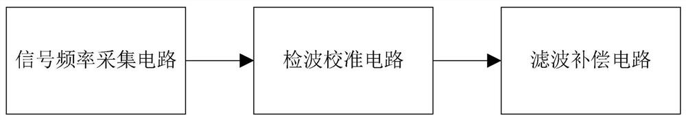
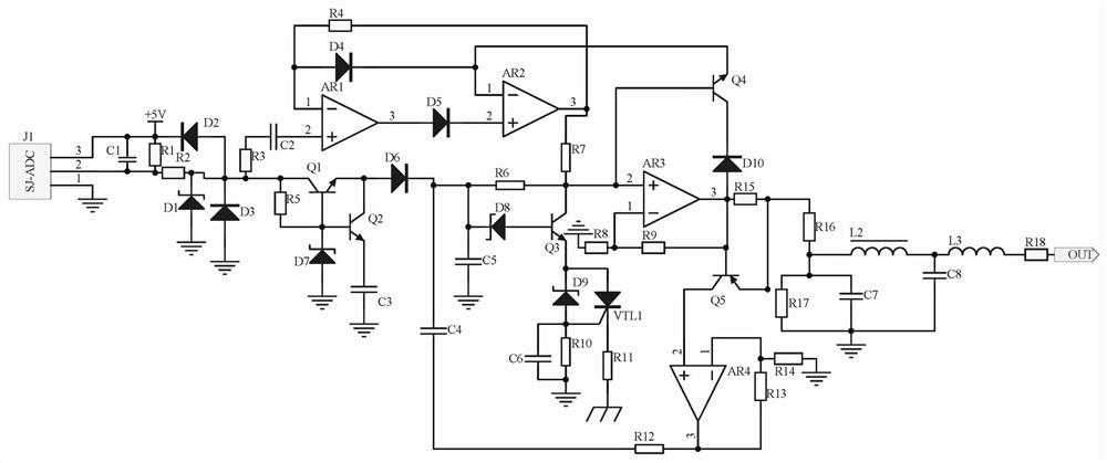
[0012] The first embodiment is a performance test device based on antiferroelectric materials, including a signal frequency acquisition circuit, a detection calibration circuit, and a filter compensation circuit. The signal frequency acquisition circuit selects the signal frequency collector J1 with the model of SJ-ADC to collect data based on antiferroelectric materials. The electrical material performance test device controls the frequency of the data signal received by the terminal, and uses a clamping circuit composed of diode D2 and diode D3 to clamp the signal within 0-+5V. The detection and calibration circuit is divided into two reception signal frequency acquisition circuits Output signal, one way uses capacitor C2 to filter the noise of low-frequency signal, while using op amp AR1 and op amp AR2 to form a detection circuit to filter out the peak signal, the second way uses transistor Q1 and voltage stabilizer D7 composed of a transistor voltage stabilizer circuit At th...

Embodiment 2

[0015] In the second embodiment, on the basis of the first embodiment, the filter compensation circuit uses the inductor L2, the resistor R17, the capacitor C7, and the capacitor C8 to form the clutter in the output signal of the filter circuit, and then outputs the clutter to filter out the clutter in the signal. That is to compensate the data signal potential received by the control terminal in the antiferroelectric material-based performance test device to prevent signal attenuation. One end of the inductor L2 is connected to one end of the resistor R16, resistor R17, and capacitor C7, and the other end of the resistor R16 is connected to the transistor Q5. Emitter, the other end of inductor L2 is connected to one end of inductor L3 and one end of capacitor C8, the other ends of resistor R17, capacitor C7, and capacitor C8 are grounded, the other end of inductor L3 is connected to one end of resistor R18, and the other end of resistor R18 is connected to the signal Output por...


PUM


Abstract

The invention discloses a performance test device based on an anti-ferroelectric material. The performance test device comprises a signal frequency collection circuit, a wave detection calibration circuit and a wave filtering compensation circuit, wherein the signal frequency collection circuit uses a signal frequency collector J1 with the model of SJ-ADC for collecting data signal frequency received by a control terminal in the performance test device based on the anti-ferroelectric material; the wave detection calibration circuit is divided into two paths to receive signals output by the signal frequency collection circuit; a first path uses a capacitor C2 to filter away noise of low-frequency signals; a second path uses a triode Q2 and a capacitor C3 to filter away noise in high-frequency signals; finally the first path of signals and the second path of signals are input into the in-phase input end of an operation amplifier AR3; the wave filtering compensation circuit uses an inductor L2, a resistor R17, the capacitor C7 and a capacitor C8 for forming a wave filtering circuit to filter away noise waves in output signals; then, output is performed; the signals can be subjected tofrequency modulation and voltage stabilization in real time by using data signal frequency received by the control terminal in the performance test device based on the anti-ferroelectric material; and the signal distortion is prevented.

Description

Technical field [0001] The present invention relates to the field of circuit technology, in particular to a performance testing device based on antiferroelectric materials. Background technique [0002] Due to its special polarization mode, antiferroelectrics have a unique electric field induced phase transition. Antiferroelectric materials are always accompanied by significant polarization, volume and current in the process of antiferroelectric-ferroelectric phase transition. Therefore, it is expected to be applied in the fields of high-energy storage, micro-displacement control, and adjustable pyroelectric infrared detection. Therefore, the performance test of anti-ferroelectric materials is relatively strict, and the polarization intensity in the process of anti-ferroelectric-ferroelectric phase change , Volume and current changes are diverse, and with the generation of current, a magnetic field will appear, affecting the collected information, and will cause frequency hopping...

Claims


Application Information

Patent Timeline
Patent Type & Authority Patents(China)
IPC IPC(8): G01R31/00
CPCG01R31/00
Inventor 高景霞孙彩霞李慧张金平张洋洋
Owner HUANGHE S & T COLLEGE
Why Eureka
Try Eureka