A cloth wear resistance testing machine
A wear-resistant performance and testing machine technology, applied in the field of testing machines, can solve problems such as low work efficiency, cloth crumbs falling to the ground, and affecting the surrounding environment
- Summary
- Abstract
- Description
- Claims
- Application Information
AI Technical Summary
Problems solved by technology
Method used
Image

Examples
Embodiment 1
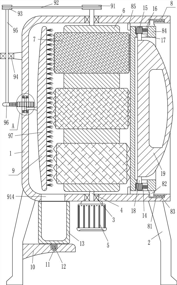
[0015] A cloth abrasion resistance testing machine, such as figure 1 As shown, it includes a frame body 1, a leg 2, a first bearing seat 3, a first rotating shaft 4, a drive motor 5, a roller 6, an annular grinding disc 7 and a fixing device 8, and the outer bottom of the frame body 1 is symmetrical on the left and right sides. The outrigger 2 is fixedly connected with the outrigger 2, and the frame body 1 is connected with the outrigger 2 through bolt connection. The first bearing seat 3 is embedded in the middle of the top and bottom of the frame body 1, and the first rotating shaft 4 is connected to the upper and lower sides. The bearing connection of the first bearing seat 3, the first rotating shaft 4 is fixed with a roller 6, the roller 6 is located in the frame body 1, and the outer surface of the roller 6 is evenly spaced with three ring-shaped grinding discs 7 with different roughness, the frame body 1. A drive motor 5 is installed vertically in the middle of the oute...
Embodiment 2
[0017] A cloth abrasion resistance testing machine, such as figure 1 As shown, it includes a frame body 1, a leg 2, a first bearing seat 3, a first rotating shaft 4, a drive motor 5, a roller 6, an annular grinding disc 7 and a fixing device 8, and the outer bottom of the frame body 1 is symmetrical on the left and right sides. The outrigger 2 is fixedly connected to the frame body 1. The first bearing seat 3 is embedded in the middle of the top and the bottom of the frame body 1. The first rotating shaft 4 is connected with the bearings of the first bearing seat 3 on the upper and lower sides. The first rotating shaft 4 is A roller 6 is fixedly connected, and the roller 6 is located in the frame body 1. Three ring-shaped grinding discs 7 of different roughness are fixedly connected to the outer surface of the roller 6 at even intervals. The output shaft of 5 is fixedly connected with the bottom end of the first rotating shaft 4 through a coupling, and a fixing device 8 is arr...
Embodiment 3
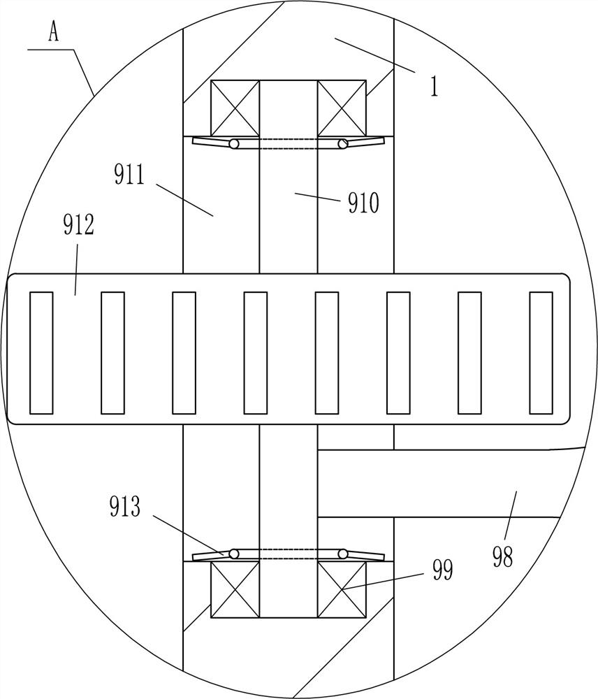
[0020] A cloth abrasion resistance testing machine, such as Figure 1-2 As shown, it includes a frame body 1, a leg 2, a first bearing seat 3, a first rotating shaft 4, a drive motor 5, a roller 6, an annular grinding disc 7 and a fixing device 8, and the outer bottom of the frame body 1 is symmetrical on the left and right sides. The outrigger 2 is fixedly connected to the frame body 1. The first bearing seat 3 is embedded in the middle of the top and the bottom of the frame body 1. The first rotating shaft 4 is connected with the bearings of the first bearing seat 3 on the upper and lower sides. The first rotating shaft 4 is A roller 6 is fixedly connected, and the roller 6 is located in the frame body 1. Three ring-shaped grinding discs 7 of different roughness are fixedly connected to the outer surface of the roller 6 at even intervals. The output shaft of 5 is fixedly connected with the bottom end of the first rotating shaft 4 through a coupling, and a fixing device 8 is ...
PUM
 Abstract
Description
Claims
Application Information
 - R&D
- Intellectual Property
- Life Sciences
- Materials
- Tech Scout
- Unparalleled Data Quality
- Higher Quality Content
- 60% Fewer Hallucinations
Browse by: Latest US Patents, China's latest patents, Technical Efficacy Thesaurus, Application Domain, Technology Topic, Popular Technical Reports.
© 2025 PatSnap. All rights reserved.Legal|Privacy policy|Modern Slavery Act Transparency Statement|Sitemap|About US| Contact US: help@patsnap.com