Clutch and control method for fracturing device

A clutch and hydraulic oil technology, applied in clutches, fluid-driven clutches, non-mechanical-driven clutches, etc., can solve problems such as safety accidents, pressure oil leakage, and difficulty in monitoring whether the clutch plate slips in the working state of the elastic connection.

Active Publication Date: 2020-07-07
中石化四机石油机械有限公司 +2
View PDF6 Cites 2 Cited by
  • Summary
  • Abstract
  • Description
  • Claims
  • Application Information

AI Technical Summary

Problems solved by technology

Chinese patent document CN107237617A describes an electric drive fracturing device with a single-machine double-pump structure. One motor drives two pump head assemblies to run, and the friction plate assembly of the clutch needs to be hydraulically driven to switch between disengagement and engagement states. , and according to the records in this document, the transmission path of the pressure oil is long, and the leakage of the pressure oil is easily caused by the influence of vibration.
[0003] In the existing clutch control, it is only possible to monitor whether the clutch is engaged or disengaged, but it is difficult to monitor the working state of the elastic connector and whether the clutch plate is slipping, and because it involves high-pressure conditions and heavy loads, it is easy to Damage to equipment and cause safety accidents, so how to detect faults in advance and reduce later losses is a technical problem that needs to be solved

Method used


Image

  • Clutch and control method for fracturing device
  • Clutch and control method for fracturing device
  • Clutch and control method for fracturing device

Examples


Embodiment 1

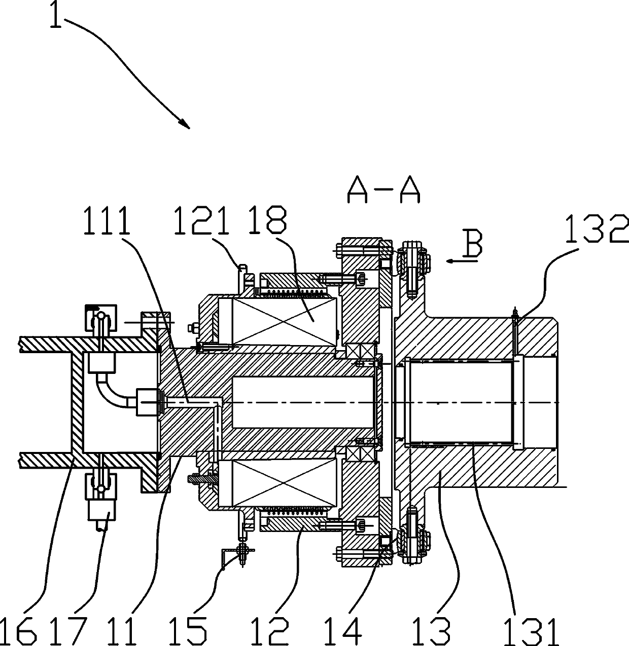
[0040] Such as Figure 2~4 Among them, a clutch for a fracturing device, which includes a pump connection part 11, a transmission part 12 and a motor connection part 13, and the pump connection part 11 and the transmission part 12 are connected in a clutchable manner through a friction plate assembly 18 , the transmission part 12 is connected with the motor connection part 13; the friction plate assembly 18 is a prior art, including a piston, a plurality of friction plates and a plurality of pressure plates for friction transmission, and is also provided with a mechanism for resetting the pressure plate The spring realizes the clutch transmission through the axial movement of a plurality of pressure plates, which are all prior art, such as the structure recorded in a tractor wet friction clutch described in the patent document CN201820235004.1, Figure 7 A schematic structural diagram of the friction plate assembly 18 is shown in , which will not be repeated here.

[0041] Th...

Embodiment 2

[0059] On the basis of Embodiment 1, a control method using the above-mentioned clutch for a fracturing device includes the following steps:

[0060] S1. When the controller issues a command, such as a PLC command, the solenoid valve 7 of the hydraulic oil circuit of the clutch 1 is turned on, and the hydraulic oil enters the oil inlet hole 111 of the clutch 1, and passes through the rotation speed of the motor 2 and the central axis of the pump head assembly 3. The speed difference between the rotating speeds judges whether the clutch 1 is engaged; at this time, after a period of time, the rotating speed of the motor 2 should be the same as the rotating speed of the central axis of the pump head assembly 3, if not, it will prompt a fault, if the time period is over, A fault is indicated. Thereby avoid the situation that clutch 1 fails. The motor 2 is provided with an angle sensor, and the sum of the angle sensor in a period of time divided by the time is the rotational speed...


PUM


Abstract

The invention provides a clutch for a fracturing device. The clutch for the fracturing device comprises a pump connecting part, a transmission part and a motor connecting part, the pump connecting part and the transmission part are connected in a separable and reunited manner through a friction plate assembly, the transmission part is connected with the motor connecting part, an oil inlet hole isformed in the end of the pump connecting part, the oil inlet hole is used for providing pressure oil for the friction plate assembly, a driving hydraulic oil connecting seat is connected with the transmission part, a flange is arranged on the side wall of the driving hydraulic oil connecting seat, an oil passing hole is formed in the flange, the oil passing hole is communicated with the oil inlethole, a hydraulic oil input device is further arranged, the hydraulic oil input device is in sliding connection with the flange in a sealed mode, and an oil inlet hole is formed in the hydraulic oil input device. According to a control method, rotating speed difference of each part of the clutch and a vibration sensor arranged are used for judging the working state of the clutch. Through the structure, the pressure oil supply path of the friction plate assembly can be shortened, and the reliability of clutch control is improved.

Description

technical field [0001] The invention relates to the field of oil drilling equipment, in particular to a clutch and a control method for a fracturing device. Background technique [0002] Fracturing is a major measure to increase production and stabilize production in the exploration and development of oil and gas fields. Multiple high-power fracturing equipment is used to fracture reservoir rocks and form diversion channels. With the development of ultra-deep well and horizontal well technology, the power of the required fracturing unit is increasing, and the weight and volume of a single fracturing equipment are also increasing. For example, the output pressure of the existing equipment reaches 175Mpa. Due to the high pressure, higher requirements are put forward for the clutch in the equipment. Chinese patent document CN107237617A describes an electric drive fracturing device with a single-machine double-pump structure. One motor drives two pump head assemblies to run, an...

Claims


Application Information

Patent Timeline
Patent Type & Authority Patents(China)
IPC IPC(8): F16D25/12F16D25/062F16D48/06
CPCF16D25/062F16D25/12F16D25/126F16D48/064F16D2500/30406
Inventor 彭平生王云海肖勇李莉莉石权刘灼范杰陆英娜
Owner 中石化四机石油机械有限公司
Why Eureka
Try Eureka