Cylindrical bearing yarn carrier and three-dimensional knitting machine adopting same
A yarn carrier and knitting machine technology, applied in the field of three-dimensional weaving, can solve the problems that the yarn carrier is easy to wear and affect the work of the three-dimensional knitting machine, and achieve the effects of reducing frictional resistance, small error in driving position, and ensuring wear resistance
- Summary
- Abstract
- Description
- Claims
- Application Information
AI Technical Summary
Problems solved by technology
Method used
Image

Examples
Embodiment 1
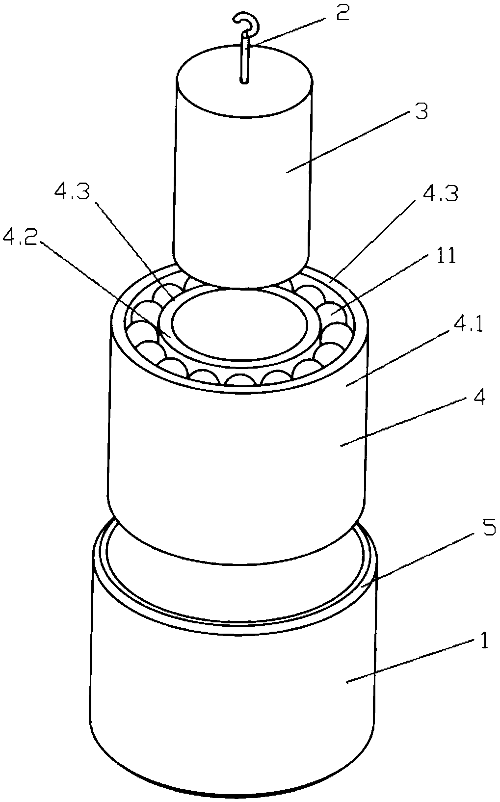
[0037] Such as figure 1 As shown, the present embodiment provides a cylindrical bearing yarn carrier, which includes a shaft sleeve 1 and a movement assembly arranged in the shaft sleeve 1 and rotatingly matched with the shaft sleeve 1, and a hook 2 for connecting the yarn is installed on the movement assembly.
[0038]Due to the rotational cooperation between the moving assembly and the shaft sleeve 1, during the movement of the cylindrical bearing yarn carrier 10, the rolling friction between the adjacent cylindrical bearing yarn carriers 10 is formed between the shaft sleeve 1 and the shaft sleeve 1, and the shaft sleeve 1 Compared with the point contact between the ball and the ball, this design structure reduces the friction resistance between the cylindrical bearing yarn carrier 10 and also ensures the wear resistance between the two effect, thereby ensuring the working accuracy of the cylindrical bearing yarn carrier 10, during the working process, the error of the driv...
Embodiment 2
[0040] This embodiment is optimized and defined on the basis of the above-mentioned embodiment 1.
[0041] Such as figure 1 As shown, the moving assembly includes a mandrel 3 fixedly connected to the lower end of the hook 2 and a bearing 4 arranged on the mandrel 3 , the bearing 4 is arranged in the shaft sleeve 1 , and the outer ring of the bearing 4 drives the shaft sleeve 1 to rotate.
[0042] Specifically, the upper end of the shaft sleeve 1 , the upper end of the bearing 4 and the upper end surface of the mandrel 3 are all flush.
[0043] Bearing 4 uses standard parts, which reduces machining errors and is easy to replace. The cylindrical bearing yarn carrier 10 can rotate at high speed, runs evenly, is wear-resistant, and runs fast. The smooth rotation of sleeve 1, the rotation can reduce the friction with the row track.
[0044] Specifically, the hook 2 is fixedly connected to the middle part of the upper end of the mandrel 3, and when the mandrel 3 keeps the axis cen...
Embodiment 3
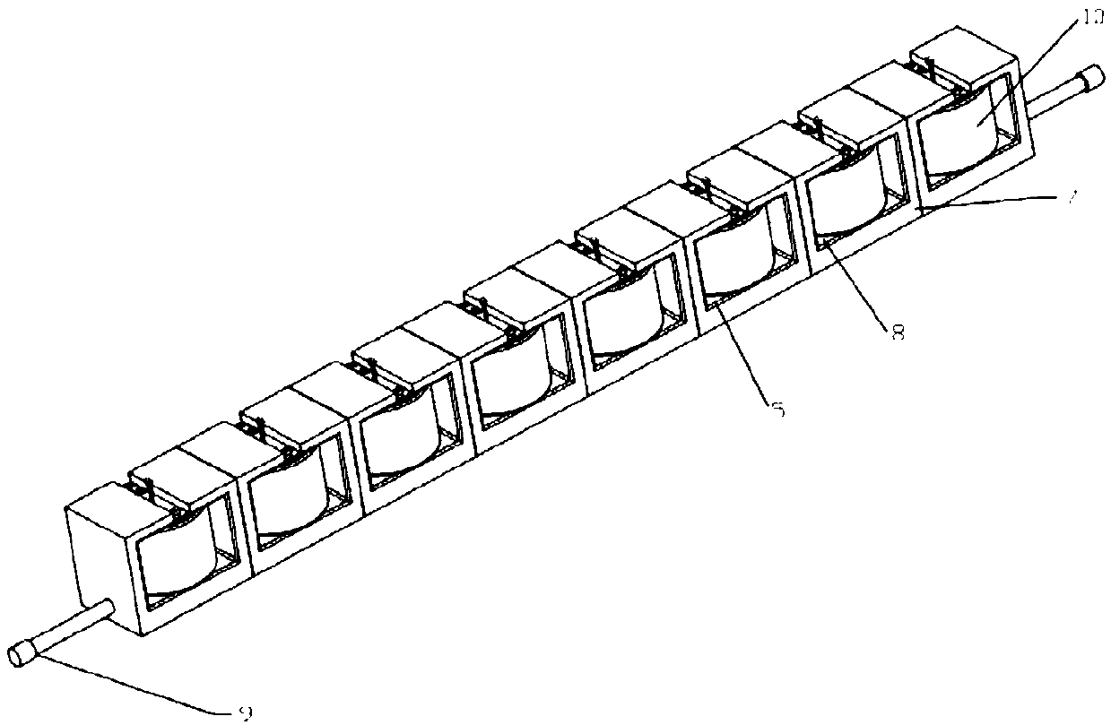
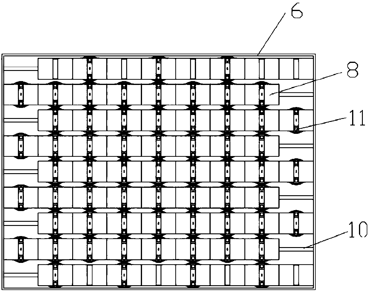
[0046] The present invention also provides a three-dimensional knitting machine using a cylindrical bearing yarn carrier 10, such as image 3 As shown, it includes a guide rail 7, a square chassis 6 for installing the guide rail 7, and a driving device for driving the guide rail 7 to move in rows and driving the cylindrical bearing yarn carrier 10 to move in columns. The two ends of the guide rail 7 in the length direction are provided with pushers Rod 9, the driving device drives the guide rail 7 through the push rod 9; when the three-dimensional braided piece is processed by the four-step process, the guide rail 7 and the cylindrical bearing yarn carrier 10 are driven by the driving mechanism 7, so that the cylindrical bearing yarn carrier 10 is in the direction of travel. Alternate reciprocating motion with a step length in the column direction.
[0047] N guide rails 7 are arranged sequentially along the width direction of the guide rails 7 and placed in the square chassis...
PUM
 Abstract
Description
Claims
Application Information
 - R&D
- Intellectual Property
- Life Sciences
- Materials
- Tech Scout
- Unparalleled Data Quality
- Higher Quality Content
- 60% Fewer Hallucinations
Browse by: Latest US Patents, China's latest patents, Technical Efficacy Thesaurus, Application Domain, Technology Topic, Popular Technical Reports.
© 2025 PatSnap. All rights reserved.Legal|Privacy policy|Modern Slavery Act Transparency Statement|Sitemap|About US| Contact US: help@patsnap.com