Bagging machine and bagging method thereof

A bagging machine and bagging technology, applied in the field of bagging machines, can solve the problems of inability to fully open the inner bag, increase the difficulty of the inner bag, high labor intensity, etc., and achieve the effects of simple structure, enriching equipment functions, and reducing labor costs.

Active Publication Date: 2019-04-05
SUZHOU HONBEST CLEAN TECH CO LTD
View PDF5 Cites 1 Cited by
  • Summary
  • Abstract
  • Description
  • Claims
  • Application Information

AI Technical Summary

Problems solved by technology

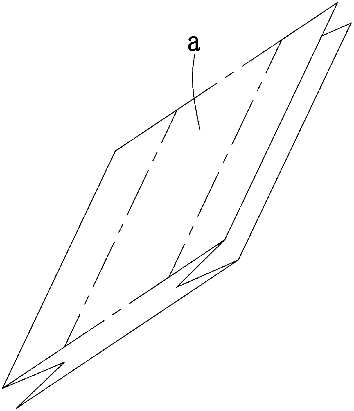
[0002] With the rapid development of solar cells and solar power generation industries, the prospect of solar-grade polysilicon and the demand for market share are growing. In the process of polysilicon processing, it is necessary to pack the broken polysilicon particles into two-layer PE bags. figure 1 As shown, the area on both sides is a four-layer folding structure, and the middle rectangular area (dotted line area) is a double-layer structure. Therefore, before bagging, it is necessary to put the inner bag into the outer bag first, and then carry out the filling. The existing work of covering the inner bag with the outer bag is basically done manually, which is labor-intensive and inefficient. Moreover, due to the structural characteristics of the PE bag itself, when a person holds the inner bag in one hand and the outer bag in the other hand, the opening of the outer bag will be damaged. It is often not fully opened, which increases the difficulty of the inner bag entering the outer bag and reduces the efficiency. Therefore, the realization of automatic bagging has become a technical problem that must be solved to improve the efficiency of polysilicon processing.

Method used


Image

  • Bagging machine and bagging method thereof
  • Bagging machine and bagging method thereof
  • Bagging machine and bagging method thereof

Examples


Embodiment Construction

[0044] Objects, advantages and features of the present invention will be illustrated and explained by the following non-limiting description of preferred embodiments. These embodiments are only typical examples of applying the technical solutions of the present invention, and all technical solutions formed by adopting equivalent replacements or equivalent transformations fall within the protection scope of the present invention.

[0045] In the description of the scheme, it should be noted that the terms "center", "upper", "lower", "left", "right", "front", "rear", "vertical", "horizontal", " The orientation or positional relationship indicated by "inner", "outer", etc. is based on the orientation or positional relationship shown in the drawings, and is only for the convenience of description and simplification of description, rather than indicating or implying that the device or element referred to must have a specific orientation , constructed and operated in a particular or...


PUM


Abstract

The invention discloses a bagging machine and a bagging method thereof. The bagging machine comprises an outer bag supplying device, a carrying platform, a conveying line, a transferring device, a bagopening device, an inner bag supplying device and a bag loading device; the outer bag supplying device is used for stacking outer bags and enabling the outer bags to be in a trapezoidal shape; the carrying platform is used for containing and fixing the outer bags; the conveying line is used for conveying the carrying platform; the transferring device is used for moving the outer bags in the outerbag supplying device to the carrying platform and makes contact with middle rectangular areas of the upper surfaces of the outer bags; the bag opening device is used for exerting upward adsorption force to the edge areas of the upper surfaces of the outer bags; the inner bag supplying device is used for stacking inner bags and enabling the inner bags to be in a trapezoidal shape; and the bag loading device is used for moving the inner bags into the outer bags on the carrying platform and makes contact with the middle rectangular areas of the upper surfaces of the inner bags. According to thescheme, the multiple mechanisms are effectively combined and linked, automatic bagging is achieved, and the bagging efficiency is effectively improved; and meanwhile, the problem that the bags are folded on the carrying platform when the bags are arranged on the carrying platform due to the fact that the two sides of the outer bags and the inner bags are hung in the air and subjected to gravity tobe significantly bent can be avoided, and effective running of the whole bagging device is guaranteed.

Description

technical field [0001] The invention relates to the field of polysilicon processing equipment, in particular to a bagging machine and a bagging method thereof. Background technique [0002] With the rapid development of solar cells and solar power generation industries, the prospect of solar-grade polysilicon and the demand for market share are growing. In the process of polysilicon processing, it is necessary to pack the broken polysilicon particles into two-layer PE bags. figure 1 As shown, the area on both sides is a four-layer folding structure, and the middle rectangular area (dotted line area) is a double-layer structure. Therefore, before bagging, it is necessary to put the inner bag into the outer bag first, and then carry out the filling. The existing work of covering the inner bag with the outer bag is basically done manually, which is labor-intensive and inefficient. Moreover, due to the structural characteristics of the PE bag itself, when a person holds the inne...

Claims


Application Information

Patent Timeline
Patent Type & Authority Applications(China)
IPC IPC(8): B65B61/00B65B43/26
CPCB65B43/26B65B61/00Y02P70/50
Inventor 陈建宝周飞
Owner SUZHOU HONBEST CLEAN TECH CO LTD
Why Eureka
Try Eureka