
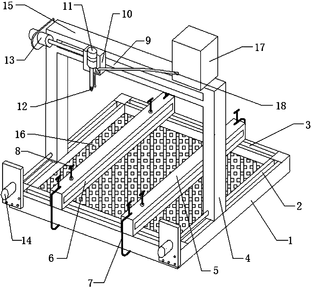
Automatic drilling device

A technology of drilling device and drill bit, applied in boring/drilling, drilling/drilling equipment, maintenance and safety accessories, etc. The effect of reducing heat, convenient drilling operation and high positioning accuracy

Inactive Publication Date: 2019-04-05
XINCHANG DINGSHI TECH CONSULTING SERVICE CO LTD
View PDF0 Cites 4 Cited by
  • Summary
  • Abstract
  • Description
  • Claims
  • Application Information

AI Technical Summary

Problems solved by technology

The position of the drill on the machine tool of the current plate drilling device is fixed. Due to the limitation of this structure, the plate needs to be moved or turned over when drilling, and the position can only be continued after recalibrating the position. Not only the work efficiency is low, but also the drilled hole distance is not easy to control, and it is easy to produce deviations, which makes the drilling inaccurate, affects the quality of the drilling, and brings inconvenience to subsequent use

Method used


Image

  • Automatic drilling device

Examples


Embodiment Construction

[0020] It should be noted that, in the case of no conflict, the embodiments of the present invention and the features in the embodiments can be combined with each other.

[0021] In describing the present invention, it should be understood that the terms "center", "longitudinal", "transverse", "upper", "lower", "front", "rear", "left", "right", " The orientations or positional relationships indicated by "vertical", "horizontal", "top", "bottom", "inner" and "outer" are based on the orientations or positional relationships shown in the drawings, and are only for the convenience of describing the present invention and Simplified descriptions, rather than indicating or implying that the device or element referred to must have a particular orientation, be constructed and operate in a particular orientation, and thus should not be construed as limiting the invention. In addition, the terms "first", "second", etc. are used for descriptive purposes only, and should not be understood ...


PUM


Abstract

The invention provides an automatic drilling device, which comprises a worktable, a supporting rod, fixing clamping plates, a first air cylinder, a second air cylinder and a third air cylinder. A first sliding rail is arranged on the worktable, and the supporting rod is slidably arranged on the first sliding rail; a cross beam is arranged at the top of the supporting rod, and a third sliding railis arranged on the side wall of the cross beam; a sliding block is slidably arranged on the third sliding rail, and the first air cylinder stretching out and drawing back in the vertical direction isarranged on the sliding block; a drill bit is arranged at the end of a retractable rod of the first air cylinder, and the second air cylinder stretching out and drawing back in the horizontal direction is arranged on the cross beam; the second air cylinder is connected with the sliding block through a retractable rod; and a second sliding rail perpendicular to the first sliding rail is further arranged on the worktable, and the two or more fixing clamping plates are slidably arranged on the second sliding rail. The automatic drilling device is convenient to operate and easy to control, manualoperation of workers is not needed, the drilling efficiency is improved, and the potential safety hazard is also effectively eliminated.

Description

technical field [0001] The invention belongs to the field of mechanical equipment, and in particular relates to an automatic drilling device. Background technique [0002] Plates are often used in mechanical products, and these plates often need to be drilled during use to facilitate the use of the plates. The position of the drill on the machine tool of the current plate drilling device is fixed. Due to the limitation of this structure, the plate needs to be moved or turned over when drilling, and the position can only be continued after recalibrating the position. Not only the working efficiency is low, but also the drilled hole distance is not easy to control, and it is easy to produce deviations, which makes the drilling inaccurate, affects the quality of the drilling, and brings inconvenience to subsequent use. Contents of the invention [0003] In view of this, the present invention aims to provide an automatic drilling device that is easy to use, high in drilling e...

Claims


Application Information

Patent Timeline
Patent Type & Authority Applications(China)
IPC IPC(8): B23B39/00B23B39/10B23Q11/10
CPCB23B39/006B23B39/10B23Q11/10
Inventor 肖翠艳
Owner XINCHANG DINGSHI TECH CONSULTING SERVICE CO LTD
Learn More