
Copper wire bending machine

A bending machine and copper wire technology, applied in the field of copper wire bending devices, can solve the problems of unsatisfactory bending position and angle accuracy, poor product consistency, and high labor intensity, so as to achieve good bending effect and improve Production efficiency and the effect of reducing labor intensity

Pending Publication Date: 2019-04-05
SUZHOU INST OF INDAL TECH
View PDF0 Cites 6 Cited by
  • Summary
  • Abstract
  • Description
  • Claims
  • Application Information

AI Technical Summary

Problems solved by technology

[0003] The purpose of the present invention is to provide a copper wire bending machine in order to solve the above problems, so as to solve the problem that the existing copper wire bending and cutting work in the prior art is all performed manually by operators, which has low efficiency and high labor intensity. ; The accuracy of the bending position and angle is not ideal, and the product consistency is poor and other technical problems

Method used


Image

  • Copper wire bending machine
  • Copper wire bending machine
  • Copper wire bending machine

Examples


Embodiment Construction

[0027] In order to make the purpose, technical solution and advantages of the present invention clearer, the technical solution of the present invention will be described in detail below. Apparently, the described embodiments are only some of the embodiments of the present invention, but not all of them. Based on the embodiments of the present invention, all other implementations obtained by persons of ordinary skill in the art without making creative efforts fall within the protection scope of the present invention.

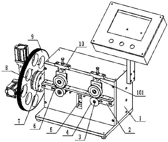
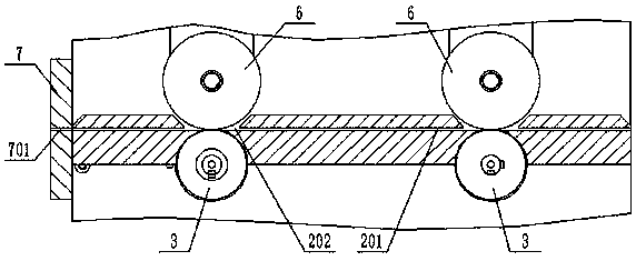
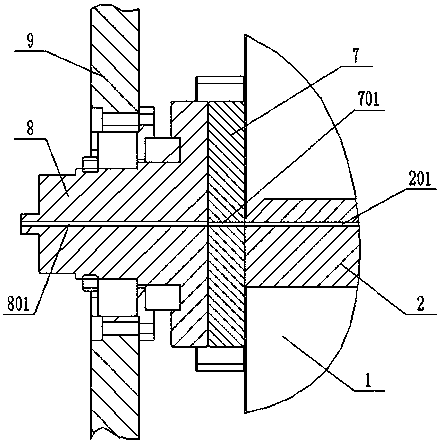
[0028] see Figure 1-Figure 7 As shown, the present invention provides a copper wire bending machine, which includes a box body 1, a conveying plate 2 is installed horizontally on the front side of the box body 1, and a conveying trough 201 is arranged inside the conveying plate 2, and the conveying trough 201 runs through the length of the conveying plate 2 At both ends of the direction, the inside of the conveying plate 2 is provided with an installation gap ...


PUM


Abstract

The invention discloses a copper wire bending machine. The copper wire bending machine comprises a box body, wherein a conveying plate is mounted on the front side of the box body; a conveying grooveis formed in the conveying plate; driving shafts are mounted on the front side of the box body in a penetration manner; conveying wheels are mounted at the outer ends of the driving shafts; adjustmentgrooves are formed in the front side of the box body; height adjustment components are mounted at the upper end of the box body; the bottom ends of the height adjustment components are rotatably connected with sliding blocks; pressing wheels are mounted in the sliding blocks through rotating shafts; a bearing plate is mounted on one side of the box body; a bearing shaft is mounted on the outer side of the bearing plate; a rotating disc is mounted on the outer side of the bearing shaft through a bearing; a bending component and a cutting component are mounted on the surface of the rotating disc. The copper wire bending machine has the beneficial effects that copper wires can be automatically conveyed, bent and cut, the cooper wires can be repeatedly bent at multiple angles, high and low positions of the sliding blocks can be adjusted by the height adjustment components, and the processing requirements of the copper wires with different diameters can be met by adjusting the distances between the pressing wheels and the conveying wheels.

Description

technical field [0001] The invention relates to the technical field of copper wire bending devices, in particular to a copper wire bending machine. Background technique [0002] Copper has very good conductivity and is widely used in the manufacture of wires, cables, brushes, etc. Copper wire bending is an important part of the deep processing of copper wires, and copper wires need to be bent into different shapes. However, the existing copper wire bending and cutting work is all performed manually by operators, which is inefficient and labor-intensive; the accuracy of the bending position and angle is not ideal, and the product consistency is poor. Contents of the invention [0003] The object of the present invention is to provide a copper wire bending machine in order to solve the above problems, so as to solve the problem that the existing copper wire bending and cutting work in the prior art is all performed manually by operators, which has low efficiency and high lab...

Claims


Application Information

Patent Timeline
Patent Type & Authority Applications(China)
IPC IPC(8): B21F1/00B21F11/00B21F23/00
CPCB21F1/00B21F11/00B21F23/00
Inventor 顾涛王雨婷石皋莲李春雷
Owner SUZHOU INST OF INDAL TECH
Learn More