A color blindness tester
A tester and color-blindness technology, applied in eye-testing equipment, medical science, diagnosis, etc., can solve the problems of difficult-to-test people's color-blindness test and complex methods, so as to improve the difficulty of testing, improve the efficiency of color-blindness testing, and strengthen the difficulty of testing Effect
- Summary
- Abstract
- Description
- Claims
- Application Information
AI Technical Summary
Problems solved by technology
Method used
Image

Examples
Embodiment 1
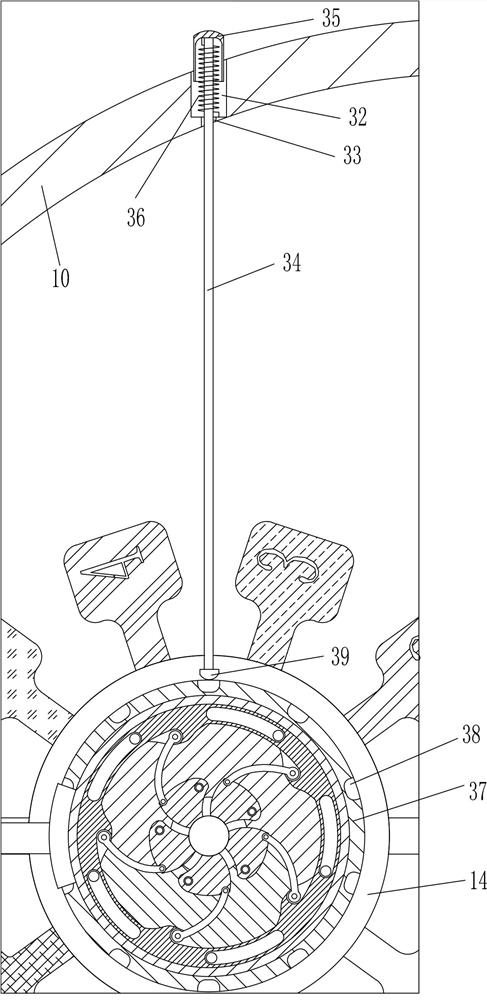
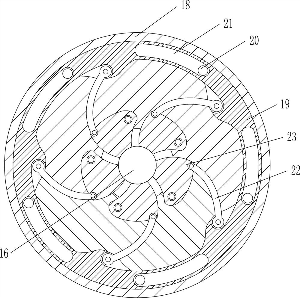
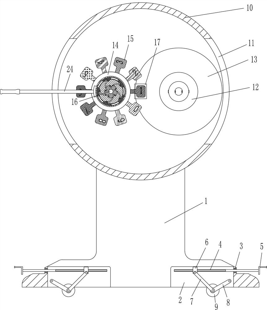
[0021] A color blindness tester such as Figure 1-2As shown, it includes a support 1, a bearing 3, a screw 4, a handle 5, a nut 6, a first connecting rod 7, a second connecting rod 8, a wheel 9, a hollow disc box 10, a chuck 12, and a color chassis 13 , the first turntable 14, the color board 15, the rotating shaft 16, the concave turntable 18, the circular slide plate 19, the pin rod 20, the third connecting rod 22, the swing block 23 and the swing bar 24, the left and right sides of the bottom of the support 1 are all open There is a first groove 2, and two bearings 3 are provided, which are respectively embedded and installed on the left and right sides of the support 1. A screw 4 is installed in the bearing 3, and the handle 5 is fixedly connected to the screw 4. The screw 4 is threaded The connection mode is connected with a nut 6, the nut 6 is located in the first groove 2, the front side of the nut 6 is connected with the first connecting rod 7 in a rotational manner, a...
Embodiment 2
[0023] A color blindness tester such as Figure 1-3 As shown, it includes a support 1, a bearing 3, a screw 4, a handle 5, a nut 6, a first connecting rod 7, a second connecting rod 8, a wheel 9, a hollow disc box 10, a chuck 12, and a color chassis 13 , the first turntable 14, the color board 15, the rotating shaft 16, the concave turntable 18, the circular slide plate 19, the pin rod 20, the third connecting rod 22, the swing block 23 and the swing bar 24, the left and right sides of the bottom of the support 1 are all open There is a first groove 2, and two bearings 3 are provided, which are respectively embedded and installed on the left and right sides of the support 1. A screw 4 is installed in the bearing 3, and the handle 5 is fixedly connected to the screw 4. The screw 4 is threaded The connection mode is connected with a nut 6, the nut 6 is located in the first groove 2, the front side of the nut 6 is connected with the first connecting rod 7 in a rotational manner, ...
Embodiment 3
[0026] A color blindness tester such as Figure 1-4 As shown, it includes a support 1, a bearing 3, a screw 4, a handle 5, a nut 6, a first connecting rod 7, a second connecting rod 8, a wheel 9, a hollow disc box 10, a chuck 12, and a color chassis 13 , the first turntable 14, the color board 15, the rotating shaft 16, the concave turntable 18, the circular slide plate 19, the pin rod 20, the third connecting rod 22, the swing block 23 and the swing bar 24, the left and right sides of the bottom of the support 1 are all open There is a first groove 2, and two bearings 3 are provided, which are respectively embedded and installed on the left and right sides of the support 1. A screw 4 is installed in the bearing 3, and the handle 5 is fixedly connected to the screw 4. The screw 4 is threaded The connection mode is connected with a nut 6, the nut 6 is located in the first groove 2, the front side of the nut 6 is connected with the first connecting rod 7 in a rotational manner, ...
PUM
 Abstract
Description
Claims
Application Information
 - R&D
- Intellectual Property
- Life Sciences
- Materials
- Tech Scout
- Unparalleled Data Quality
- Higher Quality Content
- 60% Fewer Hallucinations
Browse by: Latest US Patents, China's latest patents, Technical Efficacy Thesaurus, Application Domain, Technology Topic, Popular Technical Reports.
© 2025 PatSnap. All rights reserved.Legal|Privacy policy|Modern Slavery Act Transparency Statement|Sitemap|About US| Contact US: help@patsnap.com