Eureka AIR delivers breakthrough ideas for toughest innovation challenges, trusted by R&D personnel around the world.

Locking mechanism

A technology of locking mechanism and locking cylinder, which is applied in the application of building locks, vehicle locks, locks, etc., can solve the problems of potential safety hazards, weak bearing capacity of locking mechanism, easy loosening, etc., and achieve good practicability

Inactive Publication Date: 2019-04-02
SPECIAL VEHICLE TECH CENT OF HUBEI AEROSPACE TECH RES INST
View PDF12 Cites 5 Cited by
  • Summary
  • Abstract
  • Description
  • Claims
  • Application Information

AI Technical Summary

Problems solved by technology

[0002] At present, the locking mechanisms of the doors and windows of most off-road vehicles, special vehicles, and commercial vehicles are mostly of the lock body locking type, or are realized in the form of additional related fixing structures, but because the existing locking mechanisms have limited installation space. Higher requirements, usually only one locking mechanism is installed to fix the doors and windows, which will limit the use of most off-road vehicles, special vehicles and commercial vehicles in harsh environments, especially when passing through complex road sections When the load capacity of the single locking mechanism is not strong, it is easy to loosen, causing potential safety hazards

Method used


Image

  • Locking mechanism
  • Locking mechanism
  • Locking mechanism

Examples


Embodiment Construction

[0027] The following will clearly and completely describe the technical solutions in the embodiments of the present invention with reference to the accompanying drawings in the embodiments of the present invention. Obviously, the described embodiments are only some, not all, embodiments of the present invention. Based on the embodiments of the present invention, all other embodiments obtained by persons of ordinary skill in the art without making creative efforts belong to the protection scope of the present invention.

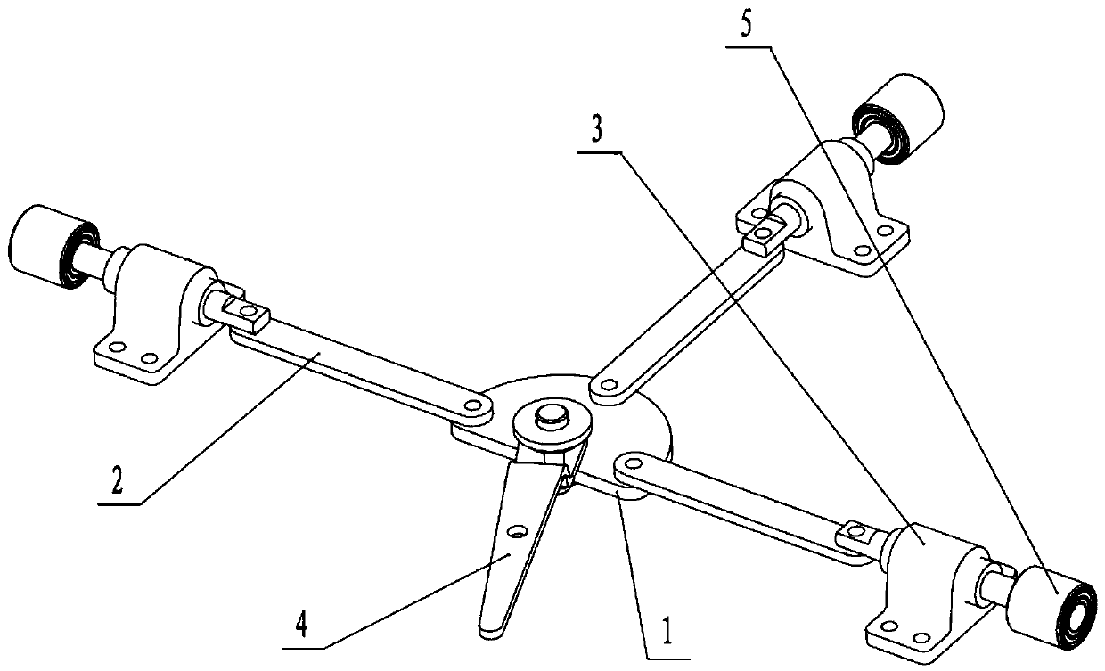
[0028] figure 1 It is a structural schematic diagram of the locking mechanism of the present invention, as figure 1 As shown, the embodiment of the present invention discloses a locking mechanism, which includes a turntable 1, a connecting rod 2, a lock cylinder seat 3, a handle 4, a lock cylinder bushing 5 and a rotation limit sleeve 6, and the rotation limit sleeve 6 is arranged on The rotation center of the turntable 1, one end of the handle 4 is fixedly c...


PUM


Abstract

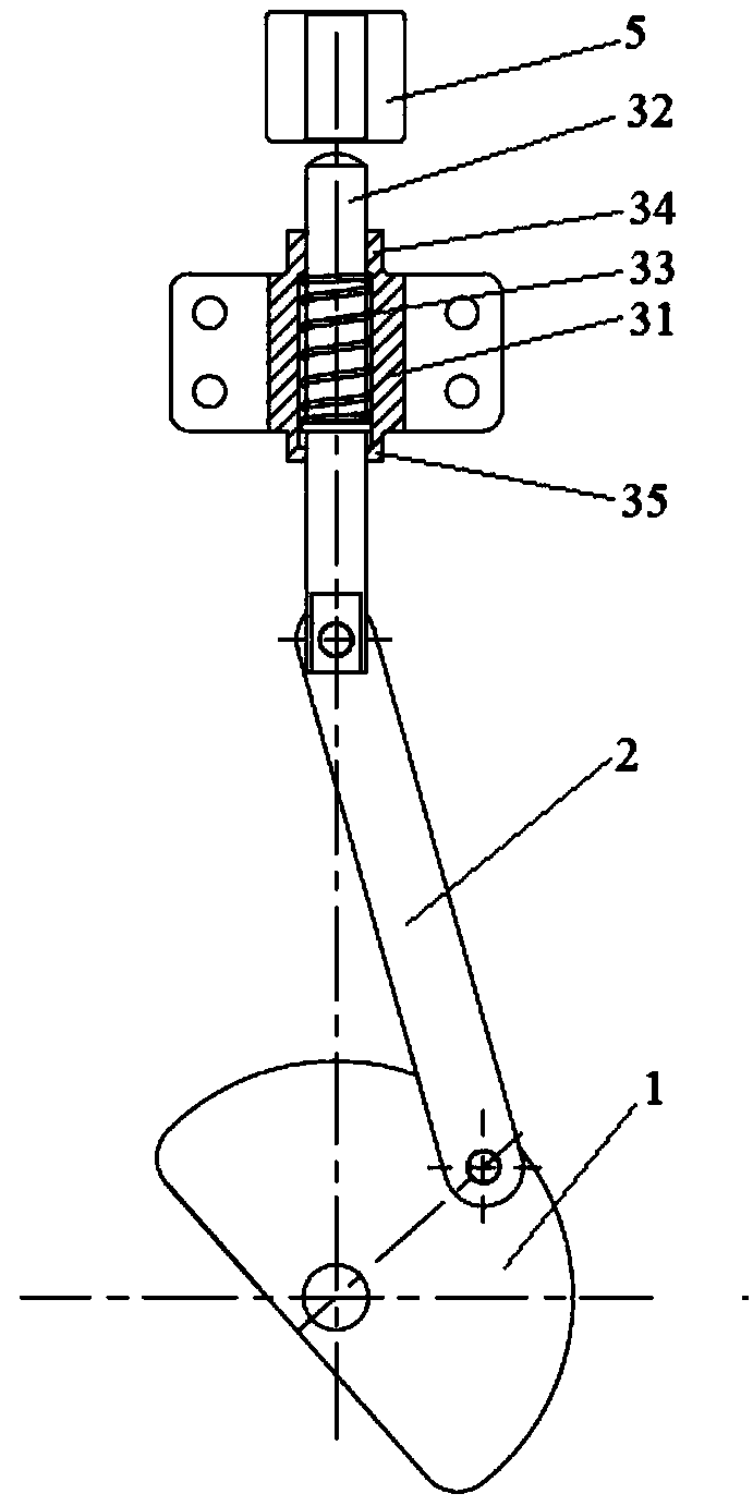
The invention provides a locking mechanism. The locking mechanism comprises a rotary table, a connecting rod, a locking column seat and a locking column bushing. Since the connecting rod is hinged tothe rotary table, when the rotary table rotates, the connecting rod can be driven to move, a locking column hinged to the other end of the connecting rod is pulled, so that the locking column can be movably inserted into the locking column bushing to realize the locking function of the locking mechanism, since a limiting spring squeezes the locking column and the locking column seat body in the locking column seat body, the locking column is separated from the locking column bushing by the elastic force of the spring, so that the unlocking function of the locking mechanism is realized, the locking mechanism can be applied to a car door and a car window, so that when a car is in a bad environment, the locking mechanism of the door and window further has certain carrying capacity, and the practicality is good.

Description

technical field [0001] The invention relates to a locking mechanism used in an automobile sunroof, in particular to a locking mechanism. Background technique [0002] At present, the locking mechanisms of the doors and windows of most off-road vehicles, special vehicles, and commercial vehicles are mostly of the lock body locking type, or are realized in the form of additional related fixing structures, but because the existing locking mechanisms have limited installation space. Higher requirements, usually only one locking mechanism is installed to fix the doors and windows, which will limit the use of most off-road vehicles, special vehicles and commercial vehicles in harsh environments, especially when passing through complex road sections , the single locking mechanism is not strong in carrying capacity and is easy to loosen, causing potential safety hazards. Contents of the invention [0003] The technical problem to be solved by the present invention is to overcome ...

Claims


Application Information

Patent Timeline
IPC IPC(8): E05C9/06E05C9/16E05B85/00
CPCE05B85/00E05C9/066E05C9/16
Inventor 韩明芳彭裕平熊旭钢裘禄邱娟
Owner SPECIAL VEHICLE TECH CENT OF HUBEI AEROSPACE TECH RES INST
Why Eureka
Eureka Blog
Learn More