
Pneumatic wire pushing take-up device

A wire take-up device, pneumatic technology, applied in the direction of transportation and packaging, conveyors, conveyor objects, etc., can solve the problems of complex mechanical claw structure, long running time, waste of energy, etc., to reduce the difficulty of electrical procedures, wire diameter span The effect of large distance and energy saving

Inactive Publication Date: 2019-04-02
江苏信泰化工装备有限公司
View PDF0 Cites 0 Cited by
  • Summary
  • Abstract
  • Description
  • Claims
  • Application Information

AI Technical Summary

Problems solved by technology

Its defects are obvious: First, when the number of take-up wires exceeds 2, the mechanical claws cannot effectively grasp the cables due to geometrical reasons
Secondly, the action is complicated and the running time is long. This structure needs to have a mechanical claw to grab the action first, and then the swing arm rotates to feed the wire into the slot.
This structure cannot effectively solve the problem that the second half of the wire is detached from the conveying belt. Generally, the mechanical claw stays above the wire receiving trough for a period of time and the wire puncher is used to solve the problem.
Thirdly, the structure of the mechanical claw is complex, and at the same time, it is necessary to add related accessories such as motor, synchronous belt, synchronous pulley, sensor, wire puncher, etc. in order to complete the related wire feeding and slotting problems, and the cost is high
Finally, the flat belt keeps moving, wasting energy

Method used


Image

  • Pneumatic wire pushing take-up device
  • Pneumatic wire pushing take-up device
  • Pneumatic wire pushing take-up device

Examples


Embodiment Construction

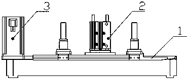
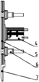
[0023] Such as Figure 1-7 As shown, the present invention provides a pneumatic wire push and take-up device, comprising a bracket 1, a take-up assembly 2 and a conveying assembly 3, the conveying assembly 3 is connected to the take-up assembly 2 through the support 1; the take-up The assembly 2 includes a cylinder 4 , a wire pushing plate 5 , a guide mechanism 6 , a guide plate 7 and a fixing seat 8 , and the cylinder 4 and the guide mechanism 6 are fixedly connected to the bracket 1 and the wire pushing plate 5 respectively.

[0024] In one embodiment, the guide mechanism 6 includes a guide rod 61, a linear bearing 62, a linear bearing fixing seat 63, a buffer pad 64, and a guide rod fixing seat 65; connected; and the guide rod 61 is connected with the pusher plate 5 through the guide rod fixing seat 65 . The guide rod 61 does and only moves linearly through the linear bearing 62 .

[0025] In another embodiment, the guide mechanism 6 includes a guide rail 611, a slider 61...


PUM


Abstract

The invention relates to a pneumatic wire pushing take-up device, comprising a bracket, a take-up assembly and a transport assembly. The take-up assembly is connected to the transport assembly by thebracket. The take-up assembly comprises an air cylinder, an air cylinder guide base and a wire pushing assembly. The air cylinder and the wire pushing assembly are respectively fixedly connected to the air cylinder guide base. The wire pushing assembly is used, when replacing wire rods in different diameters or multi-wires, components are not needed to replace, and work efficiency is greatly improved. The air cylinder is driven to realize a take-up function. Structures of a motor, a motor driver, a gear, a mechanical claw, and a swing arm are not needed, and an electrical program is reduced, and the cost is reduced. The transport assembly is conveyed by a synchronous belt, and can realize synchronization with a working state of a previous step and save energy.

Description

technical field [0001] The invention belongs to the technical field of electric equipment, and in particular relates to a pneumatic wire pushing and taking-up device. Background technique [0002] Most of the existing wire take-ups on the market adopt the structure of flat belt and rotating mechanical claw. Its defects are obvious: First, when the number of take-up wires exceeds 2, the mechanical claws cannot effectively grasp the cables due to geometrical reasons. Secondly, the action is complicated and the running time is long. This structure requires a mechanical claw to grab the action first, and then the swing arm rotates to feed the wire into the groove. This structure cannot effectively solve the problem that the second half of the wire is detached from the conveying belt. Generally, the mechanical claw stays above the wire receiving trough for a period of time and the wire punching device is used to solve the problem. Thirdly, the structure of the mechanical claw i...

Claims


Application Information

Patent Timeline
IPC IPC(8): B65G15/00B65G47/82
CPCB65G15/00B65G47/82
Inventor 张逊姜泉
Owner 江苏信泰化工装备有限公司
Learn More