
Rotary equipment rolling ring and riding wheel self turning device

A rolling ring and supporting wheel technology, which is applied in turning equipment, turning equipment, metal processing equipment, etc., can solve problems such as increased runout, unstable operation of equipment, and accelerated wear speed of grinding blocks, and achieves accurate and precise position adjustment , Convenient and fast repair processing, the effect of precision requirement restoration

Pending Publication Date: 2019-04-02
SANMENXIA CHEM MACHINERY
View PDF0 Cites 2 Cited by
  • Summary
  • Abstract
  • Description
  • Claims
  • Application Information

AI Technical Summary

Problems solved by technology

[0002] Horizontal rotary drying equipment is more and more used in industrial production, and gradually develops towards large-scale development. Since the equipment has been working under heavy load for a long time, the working surfaces of the rolling rings and supporting wheels that support the rotating parts of the equipment have been subjected to long-term handover. Due to the effect of variable load, the wear speed of the surface of the rolling ring and supporting wheel is accelerated, resulting in rough surface or offset, which increases the beating amount of the overall equipment when it rotates, increases the operating noise of the equipment, and reduces the overall service life of the equipment; large-scale rotary equipment The running of the machine is completely realized by the rolling ring and the supporting wheel, so when the rolling ring and the supporting wheel have wear and pitting, it will cause the equipment to run unstable and stop the problem. Come down to repair or replace, and cause a long repair time, it will inevitably cause a long time to stop production

Method used


Image

  • Rotary equipment rolling ring and riding wheel self turning device
  • Rotary equipment rolling ring and riding wheel self turning device

Examples


Embodiment Construction

[0012] The present invention will be further described below in conjunction with the accompanying drawings.

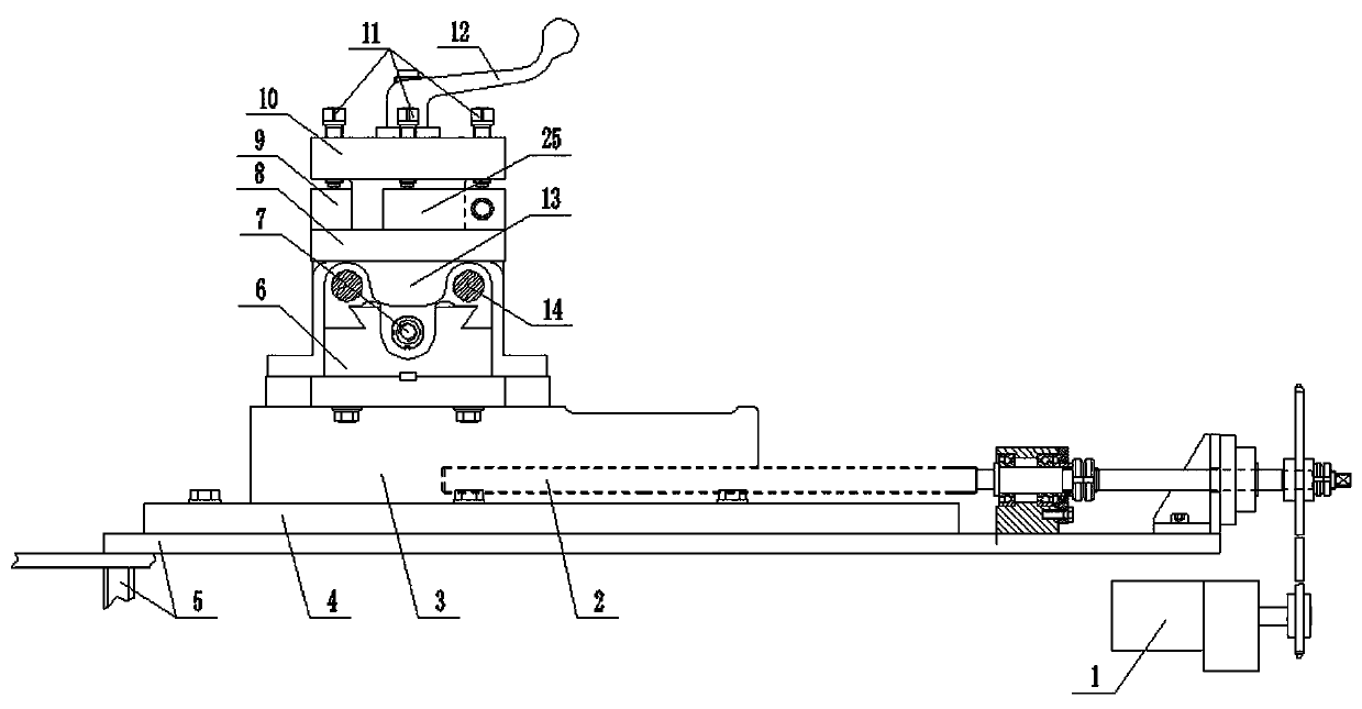
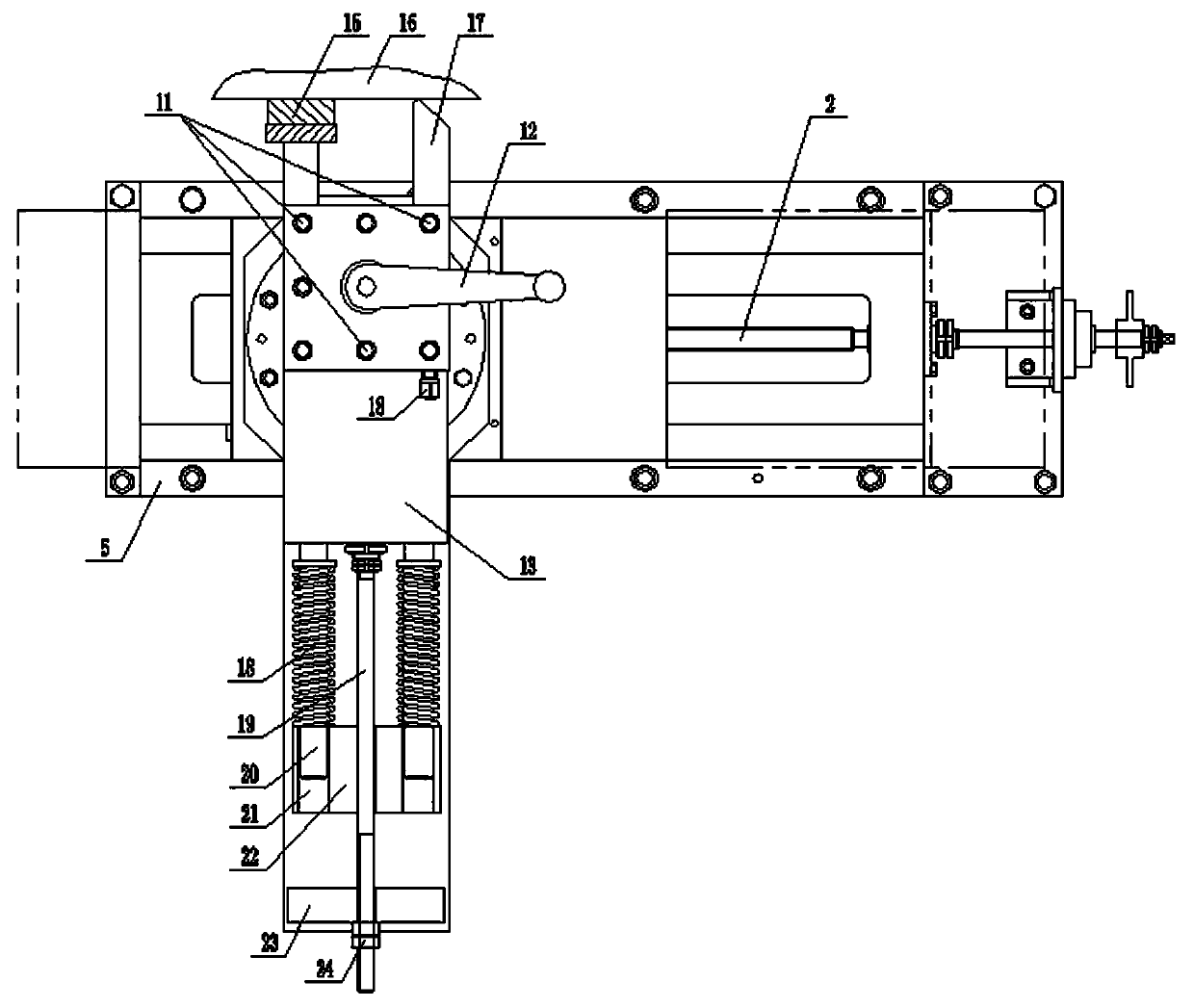
[0013] Such as figure 1 with figure 2 Shown, the present invention comprises frame 5, is provided with the longitudinal slide rail 4 that is arranged along the left and right direction on frame 5 top, is connected with longitudinal sliding seat 3 on longitudinal sliding rail 4, is fixed on longitudinal sliding seat 3 along The transverse slide rail 6 arranged in the front and back directions is slidably connected with a transverse slide seat 13 on the transverse slide rail 6, and a self-calibrating circle turning mechanism is fixed on the transverse slide seat 13; The power lead screw 2 that slides left and right on the rail 3 is fixed with a motor 1 for driving the power lead screw 2 to rotate on the frame 5 .

[0014] The self-calibrating circle turning mechanism includes a bottom plate 8 and a top plate 10, the bottom plate 8 is fixed on a transverse slide 13, an...


PUM


Abstract

The invention discloses a rotary equipment rolling ring and riding wheel self turning device which comprises a machine frame. A longitudinal sliding rail is arranged on the top of the machine frame inthe left-right direction, a longitudinal sliding base is in sliding connection with the longitudinal sliding rail, a transverse sliding rail is fixed to the longitudinal sliding base in the front-back direction, a transverse sliding base is in sliding connection with the transverse sliding rail, a self-roundness-correction turning mechanism is fixed to the transverse sliding base, a power lead screw used for driving the longitudinal sliding rail to slide left and right is rotationally connected to the machine frame, and a motor used for driving the power lead screw to rotate is fixed to the machine frame. Accordingly, the self-turning position is more accurately and more precisely adjusted, floating push for the transverse sliding base is achieved through a floating feeding mechanism, a tool works in a floating feeding mode and retreats in a floating mode when cutting resistance force is too large, the tool breaking phenomenon caused by machined surface unevenness is avoided, and a grinding block makes sliding contact with the machined surface to determine that a tool is parallel to the turned plane.

Description

technical field [0001] The invention belongs to the technical field of repairing rolling rings and supporting wheels of horizontal slewing equipment, and in particular relates to a vehicle device for rolling rings and supporting wheels of slewing equipment. Background technique [0002] Horizontal rotary drying equipment is more and more used in industrial production, and gradually develops towards large-scale development. Since the equipment has been working under heavy load for a long time, the working surfaces of the rolling rings and supporting wheels that support the rotating parts of the equipment have been subjected to long-term handover. Due to the effect of variable load, the wear speed of the surface of the rolling ring and supporting wheel is accelerated, resulting in rough surface or offset, which increases the beating amount of the overall equipment when it rotates, increases the operating noise of the equipment, and reduces the overall service life of the equipm...

Claims


Application Information

Patent Timeline
Patent Type & Authority Applications(China)
IPC IPC(8): B23B5/00
CPCB23B5/00
Inventor 祝桂林陈天斌耿海斌石占山
Owner SANMENXIA CHEM MACHINERY
Learn More