Converter valve sub-module controller and driving fault discrimination method
A technology for fault identification and sub-modules, which is applied in the direction of instruments, power transmission AC networks, measurement devices, etc., can solve problems such as false alarms of sub-module controller drive faults, and achieve the effect of improving reliability and reducing the risk of system outages
- Summary
- Abstract
- Description
- Claims
- Application Information
AI Technical Summary
Problems solved by technology
Method used
Image
Examples
Embodiment 1
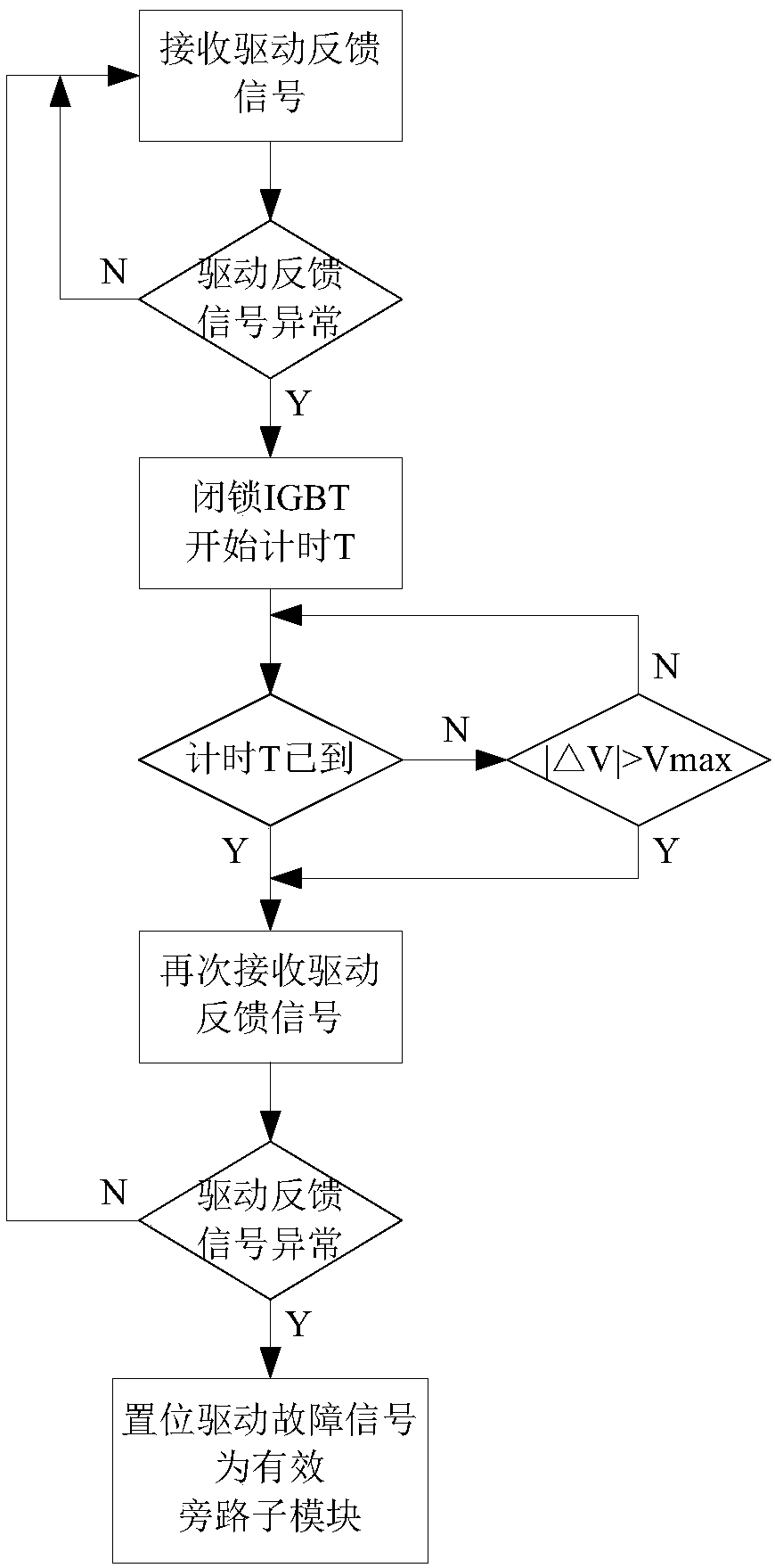
[0018] The method of this embodiment performs comprehensive judgment based on the driving feedback signal and the sub-module capacitor voltage, and is a driving fault discrimination and optimization judgment method. The flow chart is as follows figure 1 As shown, the steps are as follows:
[0019] 1. The sub-module controller receives the drive feedback signal and judges whether the drive feedback signal is abnormal: if the drive feedback signal is abnormal, set the drive fault prediction signal to be valid; if the drive feedback signal is normal, then perform step 1 again .
[0020] 2. After the drive fault prediction signal is valid, the sub-module controller issues an IGBT lock command to avoid fault expansion; at the same time, the sub-module controller records the sub-module capacitor voltage V0 at the current moment.
[0021] 3. The sub-module controller starts timing, and the timing duration is the set time T.
[0022] 4. Within the set time T, determine whether the s...
Embodiment 2
[0027] The difference from Embodiment 1 is that in this embodiment, the capacitor voltage of the sub-module is no longer used to judge the driving fault of the converter valve sub-module, and the steps are as follows:
[0028] 1. The sub-module controller receives the drive feedback signal and judges whether the drive feedback signal is abnormal: if the drive feedback signal is abnormal, set the drive fault prediction signal to be valid; if the drive feedback signal is normal, perform step 1 again .
[0029] 2. After the drive fault prediction signal is valid, the sub-module controller issues an IGBT lock command to avoid fault expansion; at the same time, the sub-module controller records the sub-module capacitor voltage V0 at the current moment.
[0030] 3. The sub-module controller starts timing, and the timing duration is the set time T.
[0031] 4. When the set time T is up, receive the drive feedback signal again and judge again: if the drive feedback signal received ag...
PUM
 Abstract
Description
Claims
Application Information
 - Generate Ideas
- Intellectual Property
- Life Sciences
- Materials
- Tech Scout
- Unparalleled Data Quality
- Higher Quality Content
- 60% Fewer Hallucinations
Browse by: Latest US Patents, China's latest patents, Technical Efficacy Thesaurus, Application Domain, Technology Topic, Popular Technical Reports.
© 2025 PatSnap. All rights reserved.Legal|Privacy policy|Modern Slavery Act Transparency Statement|Sitemap|About US| Contact US: help@patsnap.com

