A plunger suitable for horizontal wells

A technology for horizontal wells and plungers, which is applied to components of pumping devices for elastic fluids, wellbore/well components, pumps with flexible working elements, etc. Problems such as small bendability of the plunger

Inactive Publication Date: 2020-08-07
SOUTHWEST PETROLEUM UNIV
View PDF5 Cites 0 Cited by
  • Summary
  • Abstract
  • Description
  • Claims
  • Application Information

AI Technical Summary

Problems solved by technology

In 2011, Tong Zheng et al. developed a new type of plunger suitable for high-inclination directional wells. The plunger uses flexible materials to connect multiple plunger units in series. When the plunger passes through the curved well section, the flexible assembly bends. The plunger unit is relatively displaced to pass through the curved well section. However, due to the displacement of the plunger unit body, the overall surface structure of the plunger changes greatly, and the sealing effect in the curved well section is weak.
In 2013, Yan Yingfei et al. developed a sealed drainage and gas recovery plunger for natural gas horizontal wells. The plunger connects the single plunger bodies through stud bolts, so that the plunger can bend through the curved well section of the horizontal well. , but the bendability of the plunger in the direction parallel to the stud bolt is too small, it is difficult to adapt to the complex and changeable curved well section of the horizontal well
In 2017, Liu Yonghui and others developed a variable-diameter ball plug that can be used in directional and horizontal wells. The ball plug uses a specific structure to change the diameter so that it can pass through the curved well section of the horizontal well and directional well. However, the ball plug It is in line contact with the oil pipe, and the sealing section is too short, so the sealing performance needs to be improved

Method used


Image

  • A plunger suitable for horizontal wells
  • A plunger suitable for horizontal wells
  • A plunger suitable for horizontal wells

Examples


Embodiment Construction

[0023] In order to make the object, technical solution and advantages of the present invention clearer, the present invention will be further described in detail below in conjunction with the accompanying drawings and embodiments. It should be understood that the specific embodiments described here are only used to explain the present invention, not to limit the present invention.

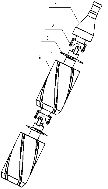
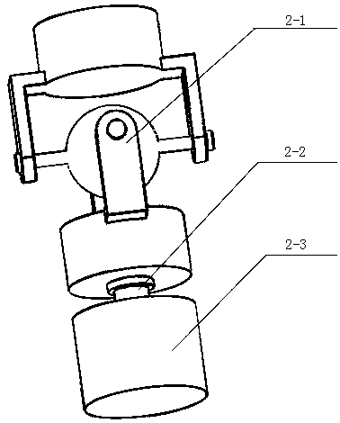
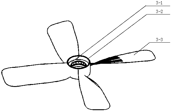
[0024] like Figure 1~4 as shown, figure 1 It is a schematic diagram of the overall structure of a plunger suitable for horizontal wells of the present invention; figure 2 It is a schematic diagram of a single plunger unit body of a plunger suitable for horizontal wells of the present invention; image 3 It is a schematic diagram of a direction-changing device for a plunger suitable for horizontal wells according to the present invention; Figure 4 It is a schematic diagram of the spiral system of a plunger suitable for horizontal wells according to the present invention; Figure 5 It is a sch...


PUM


Abstract

The invention provides a plunger applicable to a horizontal well. The plunger comprises multiple single plunger units and a fishing head, each single plunger unit comprises a gas diversion device, a deviator and a spiral system. The gas diversion device is a plunger body with a gas diversion groove; the deviator comprises a thick nipple, a thin nipple and a cardan joint; the spiral system comprises spiral blades, a fixed ring and a bearing. The plunger body, the thick nipple, the thin nipple and the cardan joint are connected in sequence from bottom to top, the spiral blades are symmetricallydistributed on the circumference of the fixed ring, and the bearing is inlaid in the fixed ring and sleeves the thin nipple. Accordingly, a new idea of changing the plunger seal turbulence generationmode is provided, the influence of the structure change to the sealing property of the plunger can be reduced, and the sealing property of the plunger passing through a curved well section is guaranteed; high turbulence is generated by means of the spiral blades, and then the sealing property in the plunger running process is effectively guaranteed. The plunger is applicable to the horizontal wellunder complex bending conditions and can effectively guarantee the sealing property at the same time.

Description

technical field [0001] The invention belongs to a plunger used in the plunger lifting technology of an oil and gas well in an oil and gas field, and specifically relates to a plunger suitable for lifting liquid by a plunger in a horizontal well. Background technique [0002] The plunger is used as a solid sealing interface to isolate the lifted liquid and gas, thereby reducing gas channeling and liquid fall, and can effectively improve the efficiency of oil and gas well lifting. At present, the plunger lifting technology is rarely used in horizontal wells. On the one hand, most of the existing plungers cannot bend and fold in their longitudinal structures, and cannot pass through the curved well section of horizontal wells, so the application in horizontal wells is limited. On the other hand, enhancing the turbulence effect during the operation of the plunger is an important factor to improve the sealing performance. The existing plungers use a fixed surface structure to mak...

Claims


Application Information

Patent Timeline
Patent Type & Authority Patents(China)
IPC IPC(8): F04B47/12F04B53/14E21B43/00
CPCE21B43/121F04B47/12F04B53/14
Inventor 刘永辉李一丰王朗王光彪吴朋勃
Owner SOUTHWEST PETROLEUM UNIV
Why Eureka
Try Eureka