Simple electrical paying-off device

A pay-off device and electrical technology, which is applied in the directions of transportation and packaging, winding strips, thin material handling, etc., can solve the problems of reducing the progress of cable pay-out construction on site, entangled cables, affecting the construction progress, etc., and achieves flexible rotation , save construction cost, and speed up the effect of unwinding speed

Pending Publication Date: 2019-03-29
CHINA CONSTR FOURTH ENG DIV INSTALLATION ENG
View PDF0 Cites 1 Cited by
  • Summary
  • Abstract
  • Description
  • Claims
  • Application Information

AI Technical Summary

Problems solved by technology

If the discharge rack is not used, the cables on site will be entangled and messy, which will not only reduce the construction progress of on-site cable discharge, but also affect the overall construction progress

Method used


Image

  • Simple electrical paying-off device
  • Simple electrical paying-off device
  • Simple electrical paying-off device

Examples


Embodiment

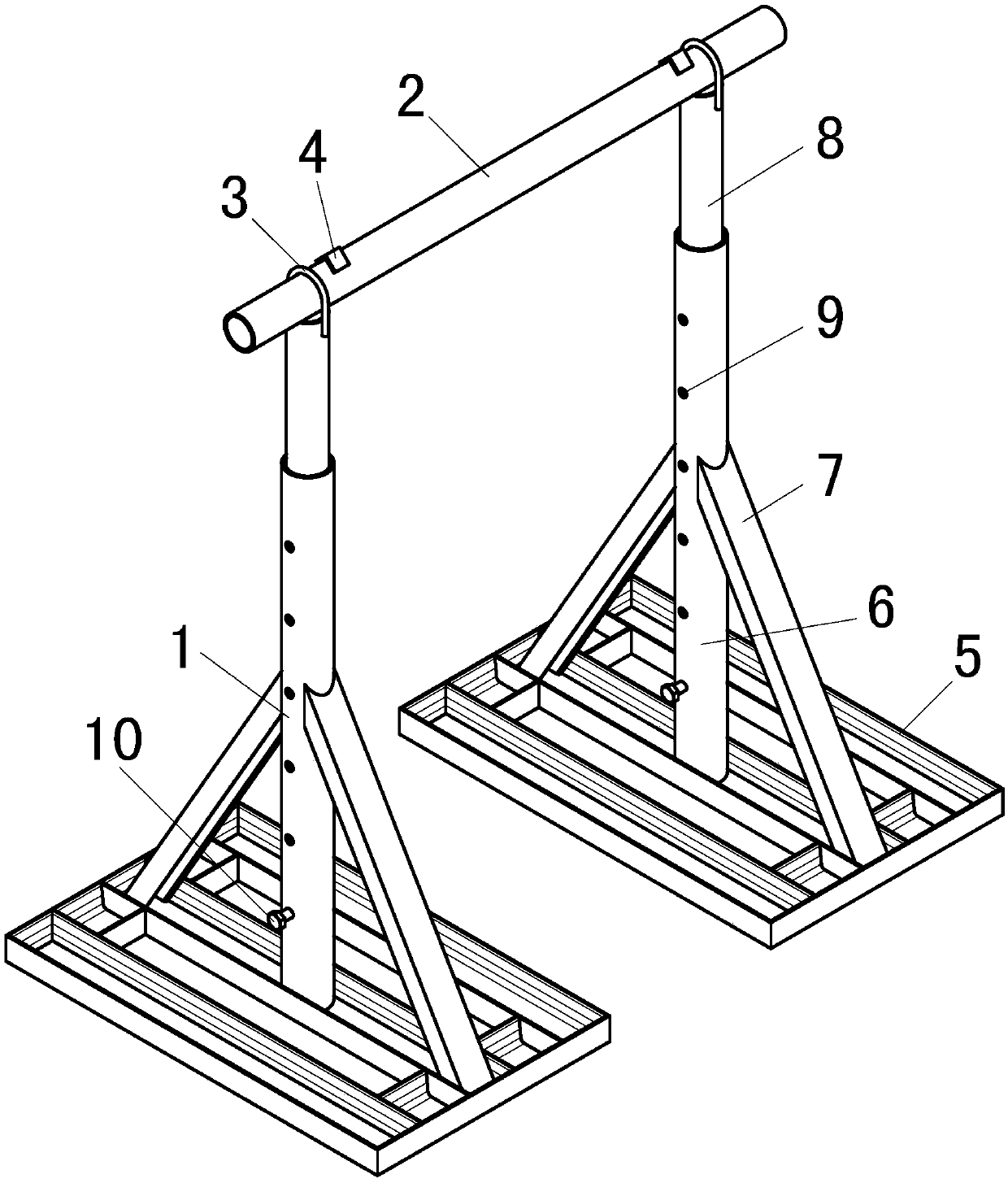
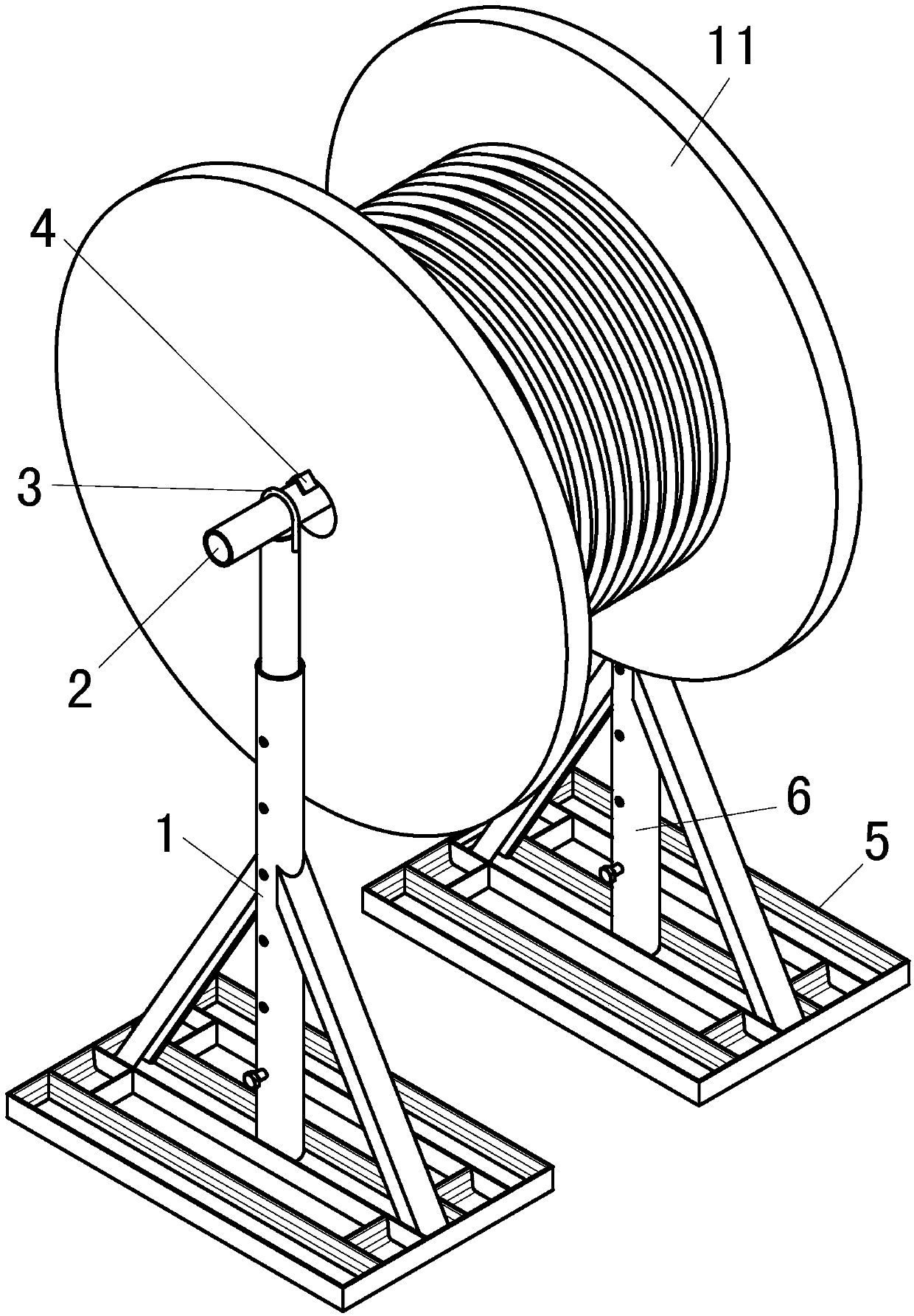
[0019] This example figure 1 and figure 2 As shown, two bases 5 are included, and each base 5 is welded by 800mm long 10# channel steel. As the outer tube 6, the outer tube 6 acts as a main support. A 1200mm DN65 galvanized steel pipe is set inside the outer pipe 6 as the inner pipe 8, which is used for telescopic adjustment of height. At the same position of the outer tubes 6 of the two bases 5, a row of positioning holes 9 of Φ16 are pierced. When adjusting the height, the height of the inner tube 8 will be fixed by penetrating the positioning screw 10 in the positioning holes 9. This can not only play a supporting role, but also adjust the height according to the specific construction site. When the height is not adjusted, the height of the inner pipe 8 should be slightly higher than the outer pipe 6, so that the top of the inner pipe 8 is connected with the horizontal pipe 2, and the inner pipe 8 is convenient for elevating and contracting. Between outer tube 6 and ba...


PUM


Abstract

The invention discloses a simple electrical paying-off device. The simple electrical paying-off device comprises a pair of supports (1), wherein a horizontal tube (2) is arranged at the tops of the supports (1), the two ends of the horizontal tube (2) are connected with the supports through U-shaped clamps (3), and limiting angle steel is arranged at the two ends of the horizontal tube (2) close to the supports. According to the simple electrical paying-off device, waste materials of a construction site are adopted, the simple electrical pay-off device is manufactured, and a special pay-off rack is replaced for paying off, so that the construction cost is saved, the paying-off speed of an on-site cable is accelerated, and the paying-off site is more regular and normative. According to thesimple electrical paying-off device, the height can be adjusted according to the size of a wire coil, and requirements of wire discs with different diameters can be met. Due to the fact that the positioning angle steel is arranged on the horizontal tube, friction between the wire coil and the supports can be avoided during pay-off, and rotation is flexible.

Description

technical field [0001] The invention relates to a simple electrical wire releasing device, which belongs to the technical field of electrical installation in building construction. Background technique [0002] At present, during electrical installation in building construction, special wire racks purchased from the market are usually used to pay out wires. Although the special pay-off frame is convenient for unwinding, it will increase the cost. If the discharge rack is not used, the cables on site will be entangled and messy, which will not only reduce the construction progress of on-site cable discharge, but also affect the overall construction progress. Contents of the invention [0003] The purpose of the present invention is to provide a simple electrical wire-releasing device, which uses the existing materials on the construction site to make a simple electrical wire-discharging frame, and solves the technical problem of on-site wire-releasing without a special wir...

Claims


Application Information

Patent Timeline
IPC IPC(8): B65H16/02
CPCB65H16/02
Inventor 陈春建朱晗刘显涛陈铮峰
Owner CHINA CONSTR FOURTH ENG DIV INSTALLATION ENG
Why Eureka
Try Eureka