
Pipe bending device, and left direction and right direction sharing pipe bender head with same

A pipe bending device and pipe bending technology, which are applied in the field of pipe bending, can solve the problems of complex structure and affect the quality of the pipe bending, and achieve the effects of improving the quality of the pipe bending, simple structure and reliable clamping force.

Inactive Publication Date: 2019-03-29
白尊敏
View PDF5 Cites 4 Cited by
  • Summary
  • Abstract
  • Description
  • Claims
  • Application Information

AI Technical Summary

Problems solved by technology

[0002] The pipe is mainly bent by a pipe bender. The existing pipe benders are divided into left-handed pipe benders, right-handed pipe benders and left-right shared pipe benders according to different bending directions. However, the existing left-right shared pipe benders The structure of the pipe bending machine is complex. When the pipe is bent into a complex shape, the bent part of the pipe will interfere with the machine, which will affect the quality of the pipe bend.

Method used


Image

  • Pipe bending device, and left direction and right direction sharing pipe bender head with same
  • Pipe bending device, and left direction and right direction sharing pipe bender head with same
  • Pipe bending device, and left direction and right direction sharing pipe bender head with same

Examples


Embodiment Construction

[0028] A number of embodiments of the present invention will be disclosed in the following figures. For the sake of clarity, many practical details will be described together in the following description. It should be understood, however, that these practical details should not be used to limit the invention. That is, in some embodiments of the invention, these practical details are not necessary. In addition, for the sake of simplifying the drawings, some well-known and commonly used structures and components will be shown in a simple schematic manner in the drawings.

[0029] It should be noted that all directional indications (such as up, down, left, right, front, back...) in the embodiments of the present invention are only used to explain the relationship between the components in a certain posture (as shown in the accompanying drawings). Relative positional relationship, movement conditions, etc., if the specific posture changes, the directional indication will also cha...


PUM


Abstract

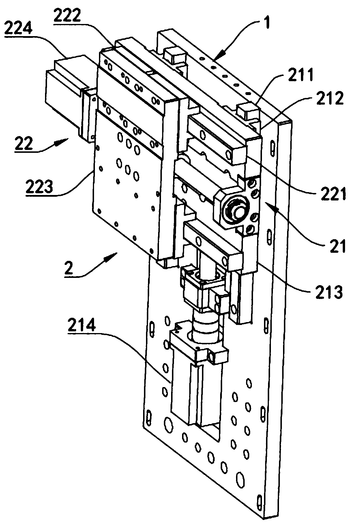
The invention discloses a pipe bending device. The pipe bending device comprises a pipe bending mechanism and a profiling mechanism. The pipe bending mechanism comprises a pipe bending driving assembly and a pipe bending assembly, and the pipe bending assembly is arranged on the pipe bending driving assembly. The profiling mechanism comprises two profiling assemblies. The two profiling assembliesare arranged on the two sides of the pipe bending driving assembly. The pipe bending assembly comprises a bending die frame, a bending die part, a die clamping Z-axis moving part and a die clamping X-axis moving part. The bending die frame is rotationally arranged on the pipe bending driving assembly through a gear shaft. The die bending part is arranged on the bending die frame. The die clampingZ-axis moving part is arranged on the bending die frame in a sliding manner. The die clamping X-axis moving part is arranged on the die clamping Z-axis moving part, and is movably connected with the bending die part. Each profiling assembly comprises a profiling Z-axis moving part, a profiling X-axis moving part and a profiling Y-axis moving part. The pipe bending device is simple in structure, and reliable and stable in clamping force, and with the pipe bending device, when a pipe is bent to be of a complex shape, bent parts of the pipe do not interfere with a pipe bender, and the quality ofpipe bending is improved then.

Description

technical field [0001] The invention relates to the technical field of pipe bending, in particular to a pipe bending device and a left-right shared pipe bending machine head provided with the pipe bending device. Background technique [0002] The pipe is mainly bent by a pipe bender. The existing pipe benders are divided into left-handed pipe benders, right-handed pipe benders and left-right shared pipe benders according to different bending directions. However, the existing left-right shared pipe benders The structure of the pipe bending machine is complex. When the pipe is bent into a complex shape, the bent part of the pipe will interfere with the machine, thus affecting the quality of the pipe bend. Contents of the invention [0003] Aiming at the deficiencies of the prior art, the invention discloses a pipe bending device, which includes: [0004] A pipe bending mechanism, which includes a pipe bending driving assembly and a pipe bending assembly, and the pipe bendin...

Claims


Application Information

Patent Timeline
Patent Type & Authority Applications(China)
IPC IPC(8): B21D7/06
CPCB21D7/06
Inventor 白尊敏唐安福
Owner 白尊敏
Learn More