
Multi-section voltage comparator

A voltage comparator and voltage comparison technology, applied in the field of electronic technology and power supply, to achieve the effects of stable working process, simple circuit principle and enhanced protection

Active Publication Date: 2019-03-26
HUNAN UNIV OF TECH
View PDF3 Cites 2 Cited by
  • Summary
  • Abstract
  • Description
  • Claims
  • Application Information

AI Technical Summary

Problems solved by technology

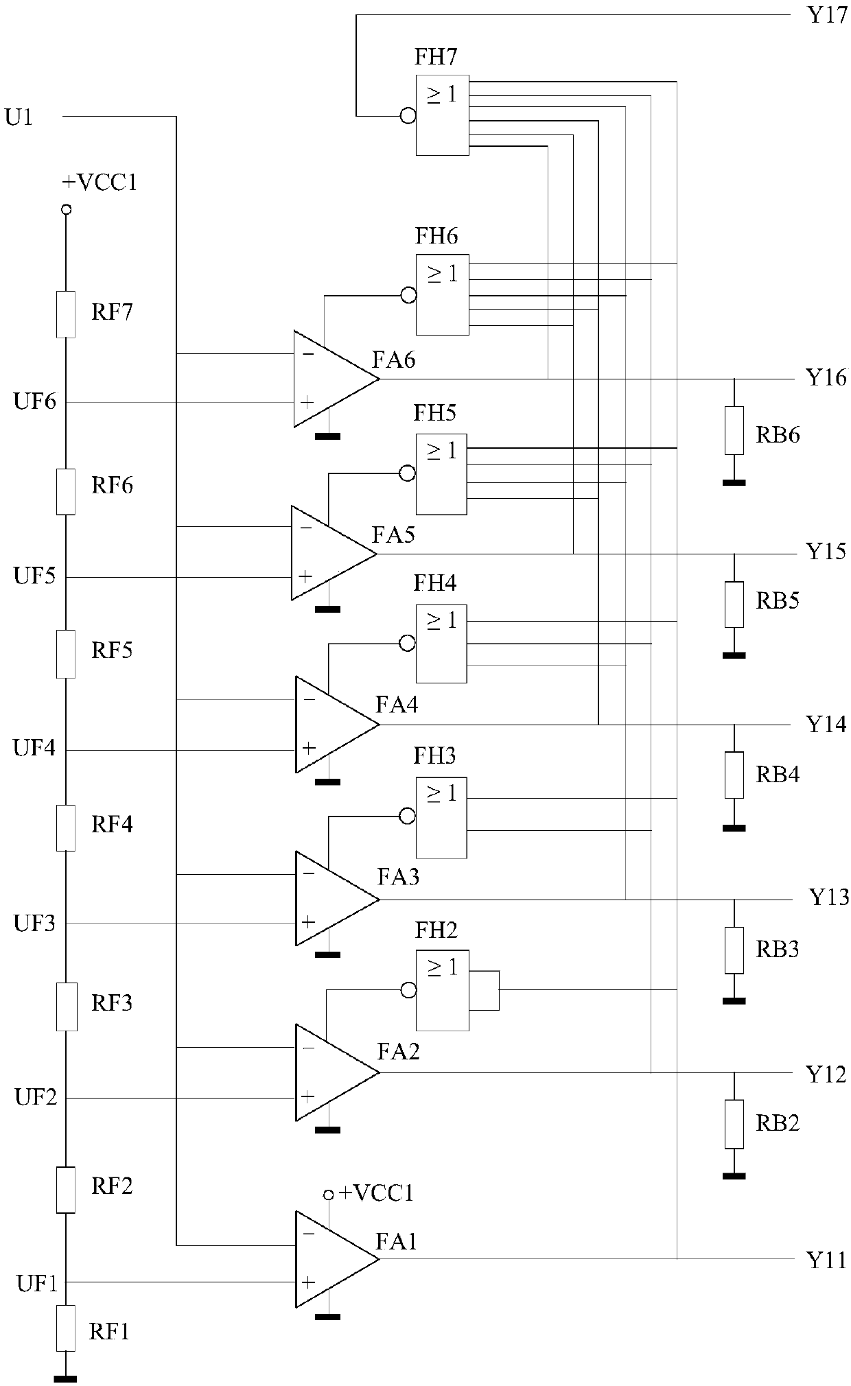
[0004] In order to solve the problems existing in the multi-interval division of the existing input voltage and the compensating AC voltage stabilizer, the present invention provides a comparator comprising M-1 A multi-interval voltage comparator, which compares the input voltage with M-1 different threshold voltages, and outputs a multi-interval voltage comparison value; M-1 different threshold voltages are respectively connected to the non-inverting input terminals of M-1 comparators , the input voltage is connected to the inverting input terminals of M-1 comparators at the same time; among the M-1 comparators, the comparator with the lowest threshold voltage is directly powered by the power supply, and the other comparators are powered by a controllable power supply; the comparator When a controllable power supply is used for power supply, only when all comparators with lower threshold voltages output low levels, the controllable power supply supplies power to its positive power supply terminal, otherwise the controllable power supply stops supplying power to its positive power supply terminal; the comparator When the controllable power supply is used for power supply and the controllable power supply stops supplying power to its positive power supply terminal, the output low level

Method used


Image

  • Multi-section voltage comparator
  • Multi-section voltage comparator
  • Multi-section voltage comparator

Examples


Embodiment Construction

[0038] The present invention will be further described below in conjunction with accompanying drawing.

[0039] figure 1 It is embodiment 1 of a multi-interval voltage comparator, and the output multi-interval voltage comparison value is composed of 7-bit binary numbers, and each bit corresponds to one of the seven voltage intervals 1-7 of the input voltage U1. figure 1 Among them, the voltage dividing resistors RF1-RF7 form a voltage dividing circuit. After dividing the voltage of the power supply +VCC1, the obtained 6 threshold voltages UF1-UF6 are 6 intermediate separation voltage values ​​that divide the input voltage U1 into 7 intervals. The six comparators FA1-FA6 realize the comparison between the input voltage U1 and the six threshold voltages UF1-UF6, and the output multi-interval voltage comparison value is composed of the output Y11-Y16 of the six comparators FA1-FA6 and the highest interval judgment value Y17. The input voltage U1 is sent to the inverting input te...


PUM


Abstract

Disclosed is a multi-section voltage comparator. A plurality of different threshold voltages is respectively connected to non-inverting input ends of a plurality of comparators. An input voltage is simultaneously connected to an inverting input end of each comparator. A comparator with the lowest threshold voltage is directly powered by a positive single power supply, and the other comparators arepowered by a controllable power supply. When the comparator is powered by a controllable power supply, the controllable power supply supplies power to the positive power supply end of the comparatoronly when all comparators whose threshold voltage is lower than the comparator output low electrical level; otherwise, the controllable power supply stops supplying power to the positive power supplyend of the comparator. When the multi-section voltage comparator is used in a compensation type alternating current voltage regulator, a sampling value of the alternating current power supply voltageis compared with a plurality of threshold voltages, and an output triggering gate control value controls the on-off combination state of a bidirectional thyristor in a thyristor switch group, so thatthe work process is stable and reliable.

Description

technical field [0001] The invention relates to the fields of electronic technology and power supply technology, in particular to a multi-interval voltage comparator. Background technique [0002] The existing compensated AC voltage stabilizer has the advantages of wide voltage stabilization range, almost no waveform distortion, high overall efficiency and strong load adaptability. Its principle is to judge the level of the input voltage, divide it into multiple voltage ranges and automatically control the switching of different winding coils of the primary winding on the compensation transformer, using the transformation ratio relationship between the primary side working winding and the secondary winding, or by adjusting the primary winding The way of applying voltage on the top provides bidirectional and multi-level voltage compensation, so as to achieve the purpose of voltage regulation and voltage stabilization. [0003] Comparing the input voltage with multiple thresh...

Claims


Application Information

Patent Timeline
IPC IPC(8): H03K3/011H03K3/017H03K5/133H03K5/26
CPCH03K3/011H03K3/017H03K5/133H03K5/26
Inventor 张晓虎凌云杨兴果
Owner HUNAN UNIV OF TECH
Learn More