
A continuously variable transmission device for transmission wheels

A technology of continuously variable speed change device and transmission wheel, which is applied in the direction of transmission device, belt/chain/gear, mechanical equipment, etc., which can solve the problems of reduced safety, excessive speed change, and less stepless speed change, and achieve reasonable structure setting, Enhanced safety and functional effects

Active Publication Date: 2020-07-28
LIUAN LONGXING AUTO PARTS
View PDF8 Cites 0 Cited by
  • Summary
  • Abstract
  • Description
  • Claims
  • Application Information

AI Technical Summary

Problems solved by technology

[0003] 1. The existing continuously variable transmissions have few forms of continuously variable transmission, which is inconvenient for further in-depth research and development;
[0004] 2. The conveyor belt in the existing continuously variable transmission sometimes has the risk of being easy to fall off, which is inconvenient to use in practice and reduces the safety of use;
[0005] 3. The transmission belt of the existing continuously variable transmission tends to become relatively loose during the process of continuously variable speed change. When the transmission belt is too loose during the speed adjustment process, the phenomenon of excessive speed change may occur

Method used


Image

  • A continuously variable transmission device for transmission wheels
  • A continuously variable transmission device for transmission wheels
  • A continuously variable transmission device for transmission wheels

Examples


Embodiment Construction

[0025] The following will clearly and completely describe the technical solutions in the embodiments of the present invention with reference to the accompanying drawings in the embodiments of the present invention. Obviously, the described embodiments are only some, not all, embodiments of the present invention. Based on the embodiments of the present invention, all other embodiments obtained by persons of ordinary skill in the art without making creative efforts belong to the protection scope of the present invention.

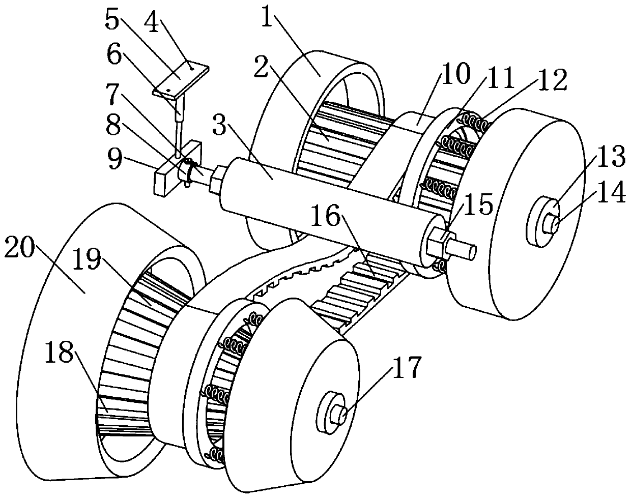
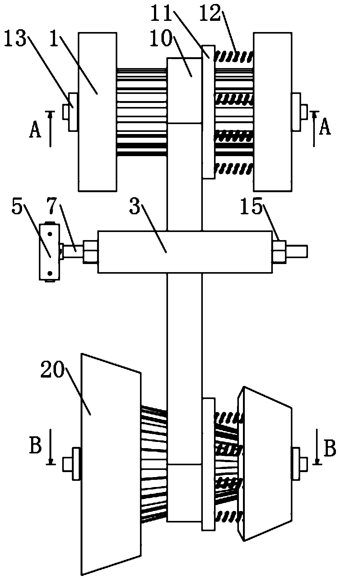
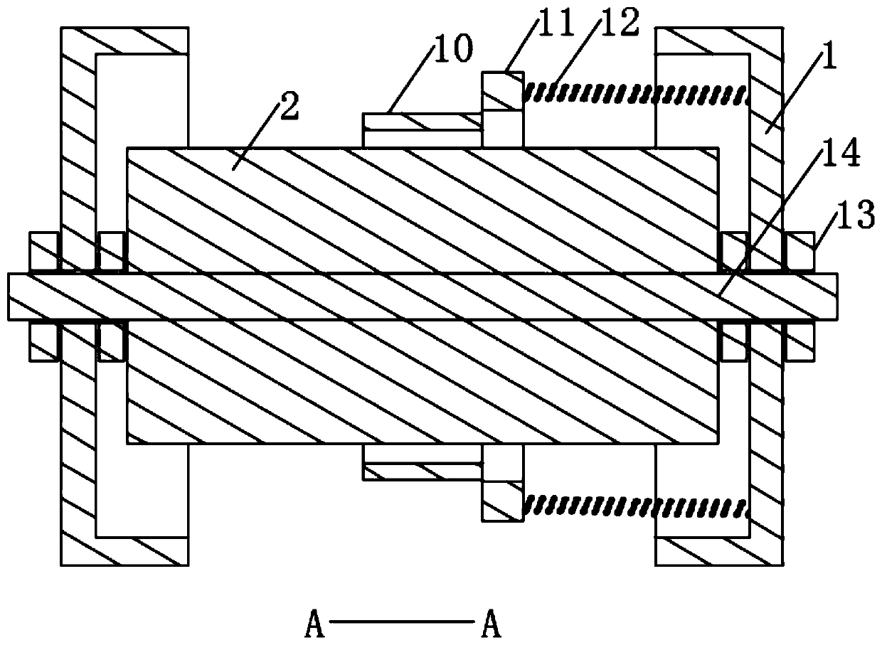
[0026] see Figure 1 to Figure 4 , the present invention provides a technical solution: a continuously variable transmission device for transmission wheels, comprising a cylindrical gear 2, a transmission belt 10, a bevel gear 19 and a pressure roller 3, the cylindrical gear 2 is a cylindrical gear arranged on a conical Just behind the gear 19, the length of the right end of the cross-section of the bevel gear 19 is less than the length of the left end, and th...


PUM


Abstract

The invention discloses a continuously variable transmission device of a transmission wheel. The continuously variable transmission device of the transmission wheel comprises a cylindrical gear, a transmission belt, a bevel gear and a press roller. The cylindrical gear is cylindrical and is arranged exactly behind the bevel gear. The length of the right end of the cross section of the bevel gear is smaller than that of the left end of the cross section of the bevel gear. Teeth which mesh with tooth grooves are arranged on the cylindrical gear and the bevel gear. By the adoption of the continuously variable transmission device of the transmission wheel, continuously variable transmission is conducted through the cooperation of the bevel gear, the cylindrical gear, the press roller and the transmission belt, the form is unique, and the deeper research and development is conducted advantageously. The press roller controls the position of the transmission belt on the bevel gear to be changed, so that the purpose of changing the transmission diameter is achieved, and then the purpose of continuously variable transmission is achieved. According to the continuously variable transmission device of the transmission wheel, rear end belt falling preventing sleeves are arranged at the two ends of the cylindrical gear in a sleeving mode, front end belt falling preventing sleeves are arranged at the two ends of the bevel gear in a sleeving mode, and therefore the risk that the transmission belt on the cylindrical gear and the bevel gear falls down is avoided, and the safety of utilization is improved.

Description

technical field [0001] The invention relates to the technical field of mechanical transmission, in particular to a continuously variable transmission device for transmission wheels. Background technique [0002] Continuously variable transmission refers to a transmission system that can continuously obtain any transmission ratio within the transmission range. The best match between the drive train and the engine operating conditions can be obtained through continuously variable transmission. Common CVTs include hydromechanical CVT, metal belt CVT and variable slope CVT, but it still has the following disadvantages in actual use: [0003] 1. The existing continuously variable transmissions have few forms of continuously variable transmission, which is inconvenient for further in-depth research and development; [0004] 2. The conveyor belt in the existing continuously variable transmission sometimes has the risk of being easy to fall off, which is inconvenient to use in pra...

Claims


Application Information

Patent Timeline
Patent Type & Authority Patents(China)
IPC IPC(8): F16H9/24
CPCF16H9/24
Inventor 刘端辉
Owner LIUAN LONGXING AUTO PARTS
Learn More