Hanger, optical fiber drawing production system and optical fiber production method

A technology of hanger and optical fiber preform, which is applied in the field of hanger and optical fiber drawing production system, which can solve the problems of poor air flow stability in the drawing furnace, difficult operation of the original tail handle and quartz tube, etc., and achieve the effect of ensuring stability

Pending Publication Date: 2019-03-26
TONGDING INTERCONNECTION INFORMATION CO LTD
View PDF3 Cites 5 Cited by
  • Summary
  • Abstract
  • Description
  • Claims
  • Application Information

AI Technical Summary

Problems solved by technology

[0006] The main purpose of the present application is to provide a hanger, an optical fiber drawing production system and an optical fiber production method. The optical fiber drawing production system adopts the second connecting piece to be suspended and connected to the first connecting piece, and the second connecting piece can be flexible around the vertical axis. The way of rotation is convenient for the original tail handle to be quickly aligned and suspended, and the design of the seal can ensure the sealing of the original tail handle and the variable diameter area, and ensure the stability of the airflow in the drawing furnace, so as to solve the problem of hanging rods in the optical fiber drawing production system in the prior art. During operation, the connection between the original tail handle and the quartz tube is difficult to operate and the air flow stability in the drawing furnace is poor.

Method used


Image

  • Hanger, optical fiber drawing production system and optical fiber production method
  • Hanger, optical fiber drawing production system and optical fiber production method
  • Hanger, optical fiber drawing production system and optical fiber production method

Examples


Embodiment Construction

[0037] Exemplary embodiments of the present disclosure will be described in more detail below with reference to the accompanying drawings. Although exemplary embodiments of the present disclosure are shown in the drawings, it should be understood that the present disclosure may be embodied in various forms and should not be limited by the embodiments set forth herein. Rather, these embodiments are provided for more thorough understanding of the present disclosure and to fully convey the scope of the present disclosure to those skilled in the art.

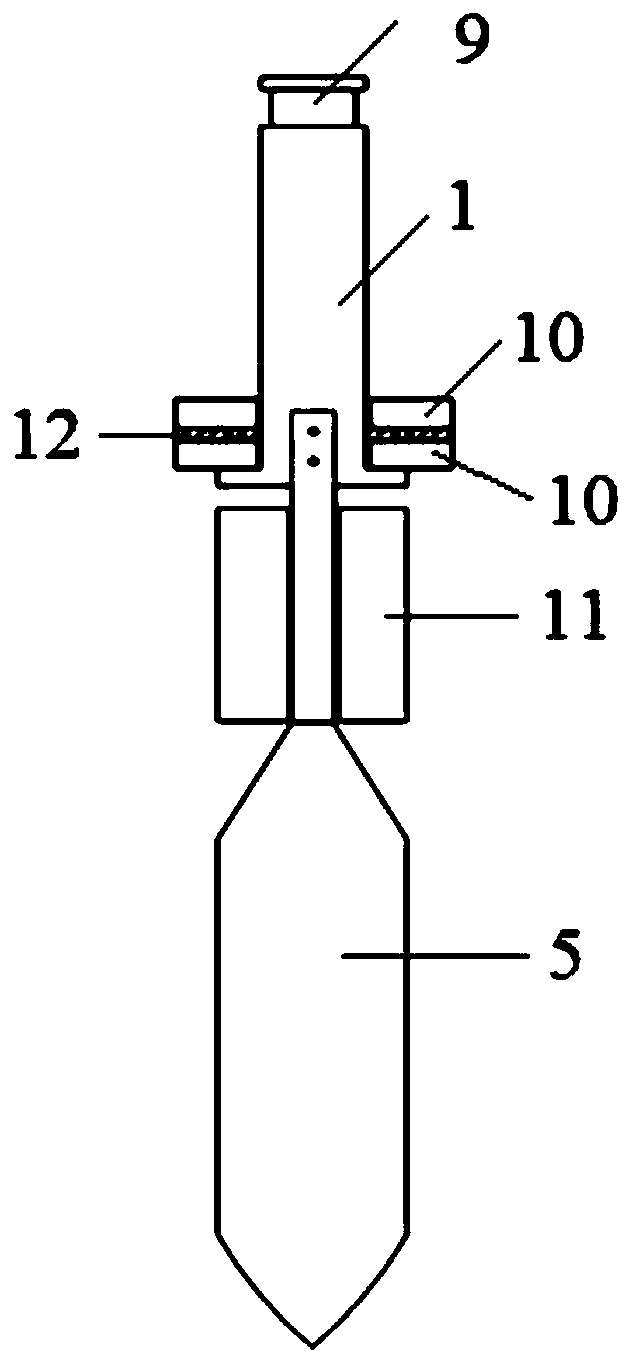
[0038] The invention discloses a hanger, such as Figure 4 As shown, this kind of hanger includes a first connecting piece 1 and a second connecting piece 2, the first connecting piece 1 is a stepped columnar body, the upper end of the upper columnar body is provided with an annular slot 9, and the diameter of the lower cylindrical body is larger than The diameter of the upper columnar body, and the lower end of the lower columnar ...


PUM


Abstract

The invention provides a hanger, an optical fiber drawing production system and an optical fiber production method. The hanger comprises a first connector and a second connector; the first connector is arranged as a stepped cylinder; an annular blocking slot is formed on circumferential surface of the upper end of an upper cylinder; the diameter of a lower cylinder is more than the diameter of theupper cylinder; a connecting slot is formed on the lower end of the lower cylinder; the second connector has an axial symmetrical structure; the upper end of the second connector is in rotating connection with the connecting slot; the second connector and the first connector are coaxially arranged; a workpiece fixing mechanism is arranged on the lower end of the second connector. The optical fiber drawing production system comprises a rod-hanging platform, a drawing furnace and the hanger. The second connector is capable of flexibly rotating around a vertical shaft, so that an original tail handle can be quickly aligned and hung, and the stability of air flow in the drawing furnace can be guaranteed by the design of sealing elements, so that the technical problems of difficulty in butt-jointing original tail handle and quartz tube in rod-hanging operation process and low stability of airflow in the drawing furnace of the optical fiber drawing production system in the prior art can besolved.

Description

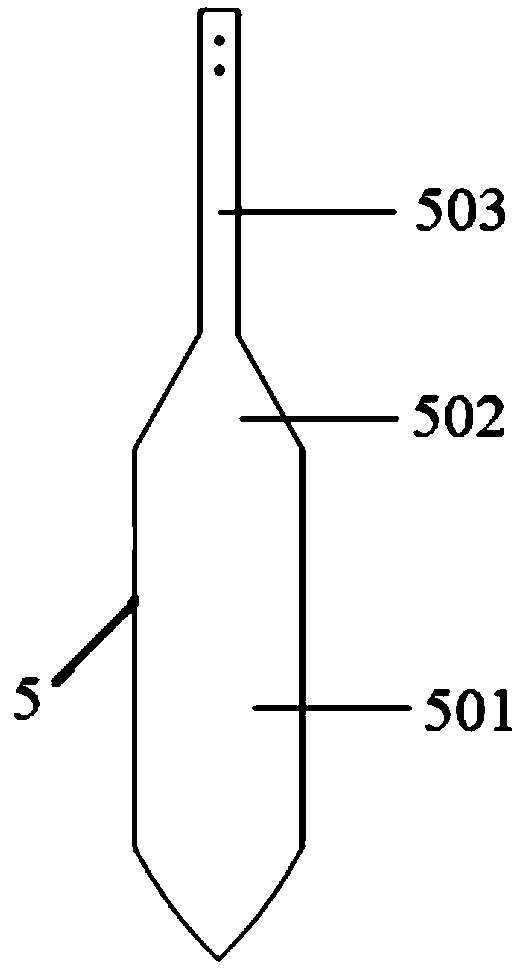
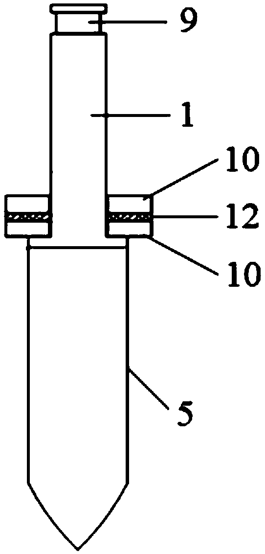
technical field [0001] The invention relates to the technical field of optical fiber production equipment, in particular to a hanger, an optical fiber drawing production system and an optical fiber production method. Background technique [0002] The optical fiber is drawn from the optical fiber prefabricated rod by high temperature heating. figure 1 As shown, the unprocessed optical fiber preform 5 with a tail generally includes a rod body 501 , a diameter reducing area 502 and an original tail 503 . Considering the compatibility between the optical fiber preform with tail handle 5 and the drawing platform, some optical fiber manufacturers will cut off the original tail handle 503 and the reducing area 502 together, and then weld a quartz tube at the end of the optical fiber preform. like figure 2 As shown, the optical fiber preform is fixed on the hanging rod platform through the annular groove 9 at the upper end of the quartz tube. In the later stage of wire drawing, a...

Claims


Application Information

Patent Timeline
Patent Type & Authority Applications(China)
IPC IPC(8): C03B37/025
CPCC03B37/025
Inventor 沈小平杨炙晟魏文涛杨志杰沈杰王樯朱坤
Owner TONGDING INTERCONNECTION INFORMATION CO LTD
Why Eureka
Try Eureka