Fusing sealing device for garbage can
A technology of sealing device and trash can, which is applied in the direction of trash cans, garbage collection, packaging, etc., can solve the problems of long waiting time, achieve the effects of halving the waiting time, increasing the success rate, and efficient and fast sealing operation
- Summary
- Abstract
- Description
- Claims
- Application Information
AI Technical Summary
Problems solved by technology
Method used
Image
Examples
Embodiment 1
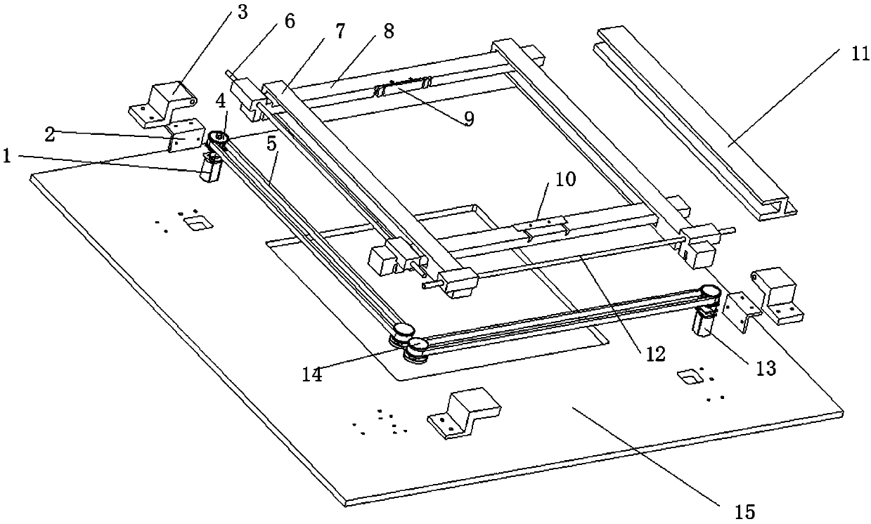
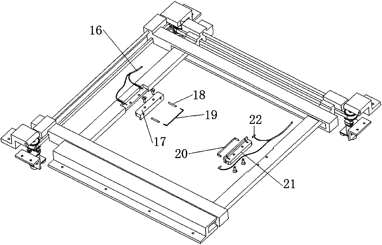
[0036] The present invention proposes a fusing and sealing device for garbage cans, which uses the combination of a mouth-shaped rod mechanism and a cross-bar mechanism to realize the fusing and sealing operations of garbage bags, making the fusing and sealing of garbage bags safer and more convenient, such as figure 1 , figure 2As shown, the following arrangement method is adopted in particular: including the cross-bar mechanism and the cross-shaped rod mechanism that cooperate with each other, and the fuse assembly arranged on the cross-bar mechanism or / and the cross-shaped rod mechanism; the cross-bar mechanism is provided with two The cross bar 8 and the cross bar actuating mechanism cooperating with the cross bar 8, the cross-shaped rod mechanism is provided with two cross-shaped rods 7 and the cross-shaped rod actuating mechanism coordinated with the cross-shaped rod 7 , the two mouth-shaped bars 7 sets are set on the two cross bars 8.
[0037] As a preferred setting s...
Embodiment 2
[0039] This embodiment is further optimized on the basis of the above-mentioned embodiments, further to better realize the present invention, such as figure 1 , figure 2 As shown, the following arrangement is adopted in particular: the crossbar actuating mechanism includes a crossbar sliding rod 6, a crossbar motor 1, two crossbar pulleys 4, and a transmission belt 5 is set on the two crossbar pulleys 4, Two crossbars 8 are sleeved on the crossbar sliding rod 6 in parallel; grooves are arranged at the same end of the two crossbars 8, and the two crossbars 8 pass through the grooves on the crossbar 8 and the crossbar pulley 4 The drive belt is matched in action, and the cross-bar motor 1 is connected with one of the cross-bar pulleys 4 in transmission.
[0040] As a preferred setting scheme, the cross-bar actuating mechanism is mainly composed of a cross-bar sliding rod 6, a cross-bar motor 1 and two cross-bar pulleys 4, and two cross-bars 8 are sleeved on the cross-bar slidi...
Embodiment 3
[0042] This embodiment is further optimized on the basis of any of the above embodiments, further to better realize the present invention, such as figure 1 , figure 2 As shown, the following arrangement is adopted in particular: one of the crossbars 8 is provided with two grooves, which can be matched with the transmission belts 5 on both sides of the crossbar pulley 4, and the other crossbar 8 is provided with a Tank body.
[0043] As a preferred setting scheme, one of the crossbars 8 is provided with two grooves, and the other is provided with a groove, and the transmission belt is divided into two sides by the crossbar pulley 4 (the drive belt section on the side of the near-mouth type bar 7 and the far-side type The drive belt section on the side of the profile bar 7) so that one of the cross bars 8 can be clamped on the transmission belt 5 on both sides of the cross bar pulley 4 at the same time, and the other cross bar 8 can be clamped on the transmission belt on the s...
PUM
 Abstract
Description
Claims
Application Information
 - R&D
- Intellectual Property
- Life Sciences
- Materials
- Tech Scout
- Unparalleled Data Quality
- Higher Quality Content
- 60% Fewer Hallucinations
Browse by: Latest US Patents, China's latest patents, Technical Efficacy Thesaurus, Application Domain, Technology Topic, Popular Technical Reports.
© 2025 PatSnap. All rights reserved.Legal|Privacy policy|Modern Slavery Act Transparency Statement|Sitemap|About US| Contact US: help@patsnap.com


