Capacitor impregnation machine

A capacitor and immersion tank technology, which is applied in the field of correcting welding devices for capacitor pins, can solve the problems of low production efficiency and slow impregnation speed, and achieve the effect of simple and reliable structure and reduced impregnation time

Inactive Publication Date: 2019-03-22
YANGZHOU SHENGYANG ELECTRONICS
View PDF0 Cites 1 Cited by
  • Summary
  • Abstract
  • Description
  • Claims
  • Application Information

AI Technical Summary

Problems solved by technology

In the prior art, during the impregnation process of capacitor elements, the impregnation speed is slow and the production efficiency is low

Method used


Image

  • Capacitor impregnation machine
  • Capacitor impregnation machine

Examples


Embodiment Construction

[0012] Below in conjunction with accompanying drawing and specific embodiment, further illustrate the present invention, should be understood that these embodiments are only for illustrating the present invention and are not intended to limit the scope of the present invention, after having read the present invention, those skilled in the art will understand various aspects of the present invention Modifications in equivalent forms all fall within the scope defined by the appended claims of this application.

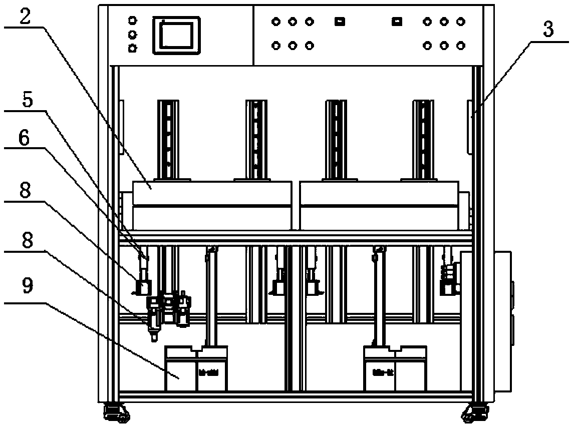
[0013] Such as figure 1 As shown, a capacitance impregnation machine includes a frame, an impregnation box, a liquid storage tank and a vacuum pump arranged on the frame, the impregnation box includes an impregnation tank and a tank cover, the impregnation tank is connected with a vacuum pump, and the impregnation The two sides of the tank are respectively provided with grooves, and the ultrasonic vibrating heads are arranged in the grooves, and the tank cover is connect...


PUM


Abstract

The invention discloses a capacitor impregnation machine. The capacitor impregnation machine comprises a rack, impregnation boxes, a liquid storage tank and a vacuum pump, wherein the impregnation boxes, the liquid storage tank and the vacuum pump are arranged on the rack; each impregnation box comprises an impregnation tank and a tank cover; the impregnation tank is connected with the vacuum pump; grooves are respectively formed in two sides of the impregnation tank; ultrasonic vibration heads are arranged in the grooves; the tank cover is connected with the impregnation tank through a driving connecting rod; the rack is provided with mounting upright columns below the impregnation tanks; the mounting upright columns are provided with first photoelectric detectors and second photoelectricdetectors through sliders disposed on the mounting upright columns; the sliders are connected with stepping motors respectively; and the driving connecting rods of the tank covers are connected withcover opening air cylinders respectively. With the capacitor impregnation machine of the invention adopted, capacitor elements can be quickly and automatically impregnated.

Description

technical field [0001] The invention belongs to the technical field of capacitor production equipment, and in particular relates to a device for rectifying and welding capacitor pins. Background technique [0002] With the rapid development of the electronics industry, capacitors are used more and more as important electronic components. In particular, the market prospect of high-end solid capacitors is becoming more and more broad, and the production of solid capacitors needs to go through cutting, nailing, rubber cover assembly, welding, chemical formation, impregnation, polymerization, sealing assembly, soaking, stamping, aging, Appearance inspection, cutting and packaging. Among them, welding is to weld the element formed after the nail is rolled with the iron bar. In this process, the element must be separated, and the defective products with polarity defects should be screened and removed. Finally, the welding height, Dimensions such as spacing are within specificatio...

Claims


Application Information

Patent Timeline
IPC IPC(8): H01G13/04
CPCH01G13/04
Inventor 王云飞黎华章
Owner YANGZHOU SHENGYANG ELECTRONICS
Why Eureka
Try Eureka