Rubber automatic dipping forming device for rubber band machining

A dipping molding and rubber band technology, which is applied in the field of rubber automatic dipping molding device for rubber band processing, can solve the problems of manual demoulding, lower processing efficiency, low processing efficiency, etc., and achieve the effect of ensuring drying effect and improving lubrication effect

Active Publication Date: 2020-05-15
安徽省潜山市创先实业有限公司
View PDF3 Cites 1 Cited by
  • Summary
  • Abstract
  • Description
  • Claims
  • Application Information

AI Technical Summary

Problems solved by technology

[0007] Aiming at the deficiencies of the prior art, the present invention provides an automatic rubber dipping and molding device for rubber band processing, which overcomes the deficiencies of the prior art, has a reasonable design and a compact structure, and aims to solve the problem of the existing rubber band preparation rubber dipping device. During operation, the processing efficiency is low, and it needs to cooperate with multiple processing personnel for auxiliary processing; and it does not have the function of automatic demoulding, and manual demoulding is required, which further reduces the problem of processing efficiency

Method used


Image

  • Rubber automatic dipping forming device for rubber band machining
  • Rubber automatic dipping forming device for rubber band machining
  • Rubber automatic dipping forming device for rubber band machining

Examples


Embodiment 1

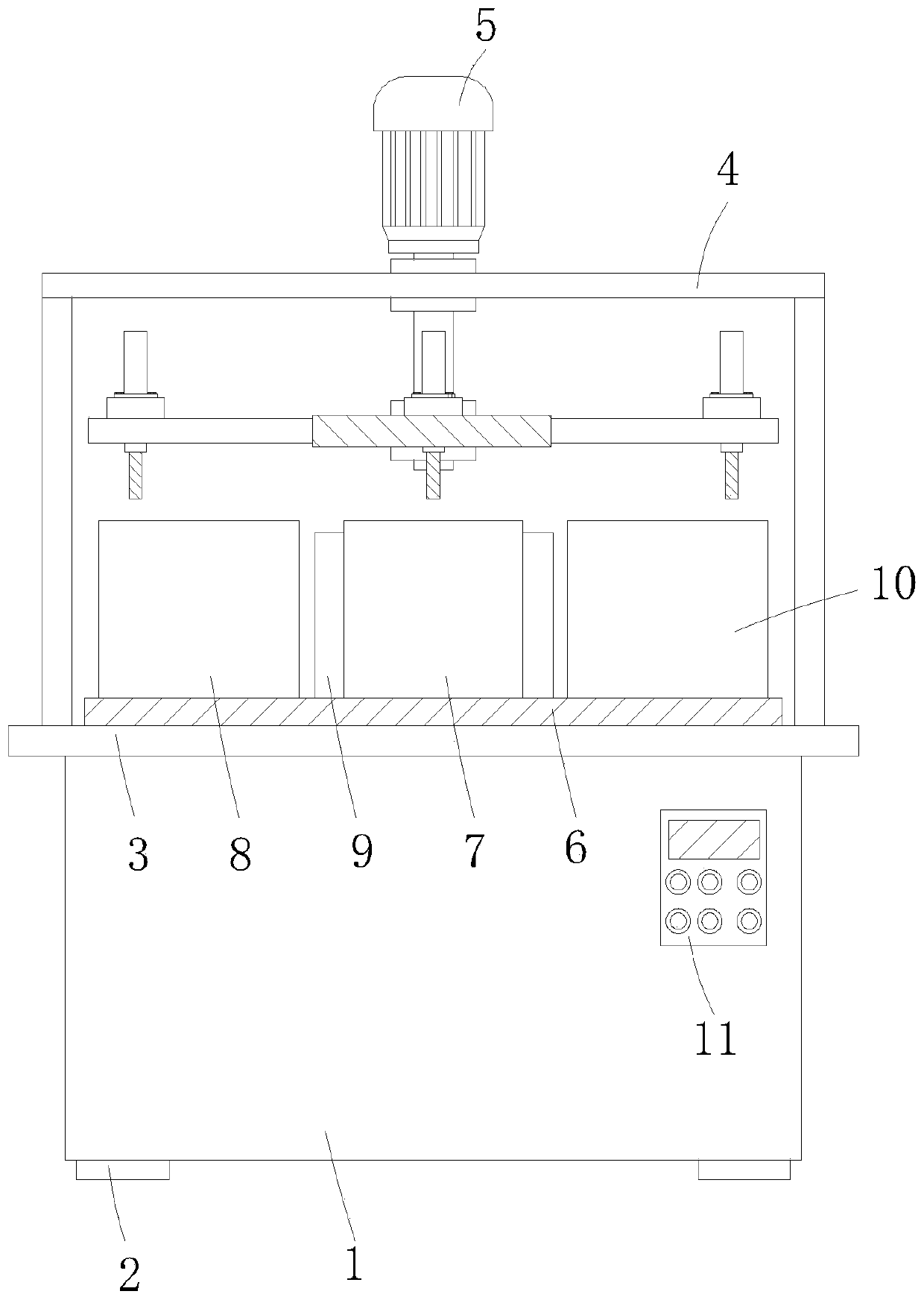
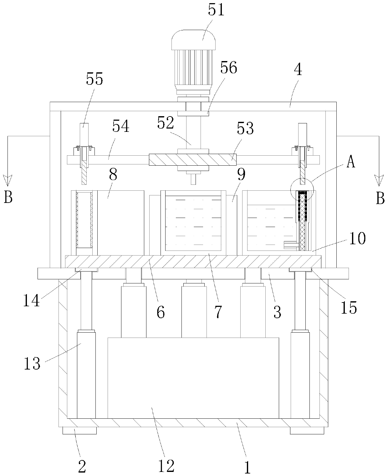
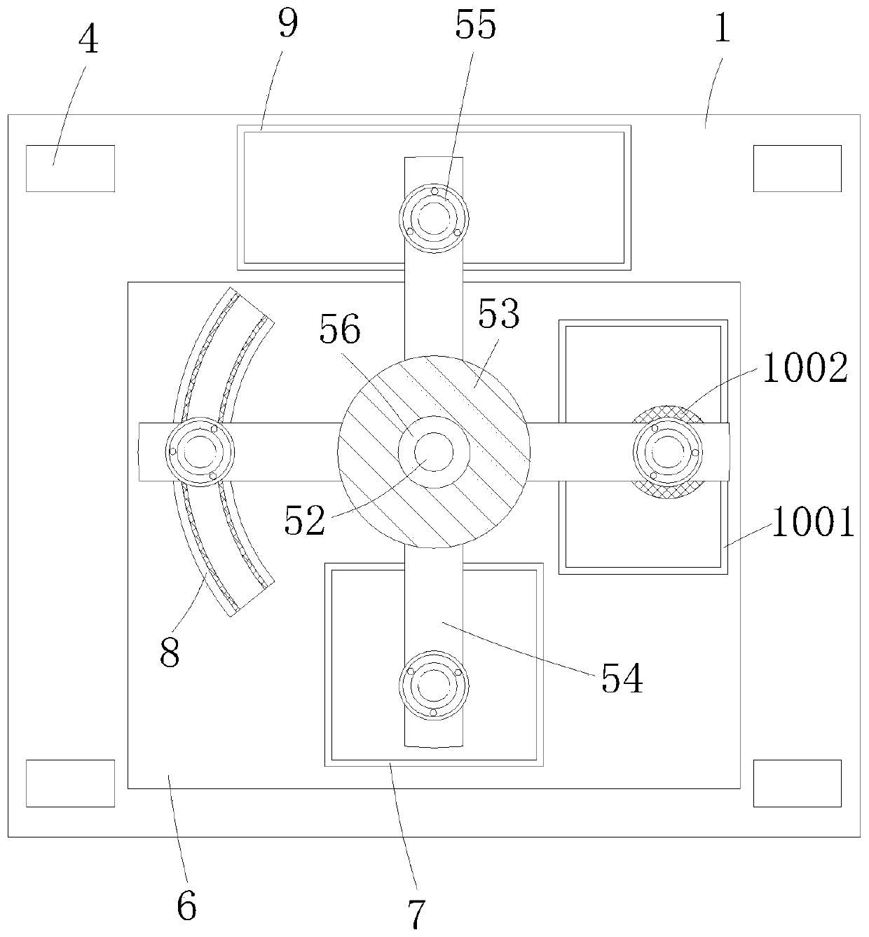
[0039] An automatic rubber dipping and molding device for rubber band processing, comprising a base box 1, a plurality of support feet 2 installed at the lower end of the base box 1, and a processing panel 3 horizontally installed at the upper end of the base box 1, and a support is installed at the upper end of the processing panel 3 Frame 4, and a rotating mechanism 5 is installed on the inner top wall of the supporting frame 4, and the rotating mechanism 5 is used for the circulation of the mold between the dipping box 7, the drying mechanism 8 and the lubricating mechanism 10 in order to ensure that the cylindrical rubber belt c Dip molding and demoulding, the bottom of the rotating mechanism 5 is provided with a lifting plate 6, and the lifting plate 6 is arranged on the upper end surface of the processing panel 3, and the upper end of the lifting plate 6 is provided with a dipping box 7, a drying mechanism 8 and a lubricating mechanism 10 , realizing the lubrication of th...

Embodiment 2

[0058] The difference between this embodiment and embodiment 1 is that, as figure 2 As shown, the upper edge of the lifting plate 6 is also equipped with a plurality of support bases 14, and the lower end of the support base 14 is vertically installed with a telescopic limit rod 13, and the lower end of the telescopic limit rod 13 extends to the inner cavity of the base box 1 And vertically installed on the inner bottom wall of the base box 1, the upper end of the processing panel 3 is provided with a plurality of preset grooves 15 matching with the support seat 14, which effectively play the role of limiting and ensure the horizontal lifting of the lifting plate 6 , so as to carry out rubber automatic dip molding.

[0059] Refer to Example 1 for other undescribed structures.


PUM


Abstract

The invention relates to the technical field of rubber band machining equipment, and provides a rubber automatic dipping forming device for rubber band machining. The problems that when an existing rubber dipping device for rubber band machining runs, machining efficiency is low, multiple machining persons need to be cooperated for auxiliary machining, the automatic demolding function is not achieved, manual demolding is needed, and the machining efficiency is further reduced can be solved. The device comprises a base box, multiple supporting pad feet mounted on the lower end of the base box and a machining panel mounted on the upper end of the base box horizontally, the upper end of the machining panel is provided with a supporting rack, a rotating mechanism is mounted on the inner top wall of the supporting rack, a lifting plate is mounted below the rotating mechanism, the lifting plate is mounted on the upper end face of the machining panel, a dipping box, a drying mechanism and a lubricating mechanism are mounted on the upper end of the lifting plate, and a jacking mechanism is mounted on the lower end of the lifting plate. The device is particularly suitable for rubber automatic dipping machining of rubber band machining, and has the higher social use value and application prospects.

Description

technical field [0001] The invention relates to the technical field of rubber band processing equipment, in particular to an automatic rubber dipping molding device for rubber band processing. Background technique [0002] Rubber band is a short loop made of rubber and latex, which is mainly used for binding items. It has the characteristics of high elongation, good resilience, low price, and convenient use. Its manufacturing process includes dipping, demoulding, vulcanization, ring cutting (strip) and other processes. [0003] Dip molding refers to the process of formulating polymer materials into rubber materials, which are used to impregnate rubber materials for models with similar product shapes, so that the rubber materials adhere to the outer surface of the model, and obtain dairy products after drying and vulcanization. When the rubber band is processed, it is first dipped and formed into a cylindrical rubber belt, and the cylindrical rubber belt is demoulded and vul...

Claims


Application Information

Patent Timeline
Patent Type & Authority Applications(China)
IPC IPC(8): B29C41/14B29C37/00
CPCB29C41/14B29C37/0092B29C37/0067
Inventor 杜传来邹儒平田五四
Owner 安徽省潜山市创先实业有限公司
Why Eureka
Try Eureka