
Deformation parameter testing test bench for deformation wing

A technology of parameter testing and test bench, which is applied to the test platform for measuring deformation parameters of deformed wings, and the field of measurement of displacement and stress deformation parameters. It can solve the problems of long cycle and high cost, and achieve simple operation, low cost and reduced measurement time. Effect

Inactive Publication Date: 2019-03-22
NORTHWESTERN POLYTECHNICAL UNIV
View PDF7 Cites 13 Cited by
  • Summary
  • Abstract
  • Description
  • Claims
  • Application Information

AI Technical Summary

Problems solved by technology

Generally, wind tunnel tests are commonly used to test wings, but there are problems such as high cost and long period.

Method used


Image

  • Deformation parameter testing test bench for deformation wing
  • Deformation parameter testing test bench for deformation wing
  • Deformation parameter testing test bench for deformation wing

Examples


Embodiment Construction

[0021] This embodiment is a test bench for testing deformation parameters of deformed wings.

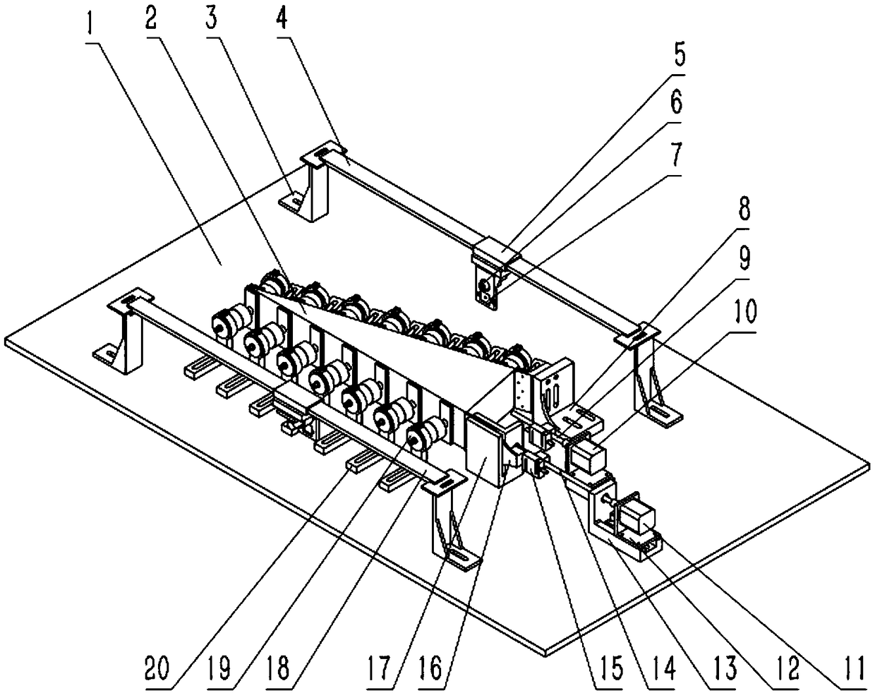
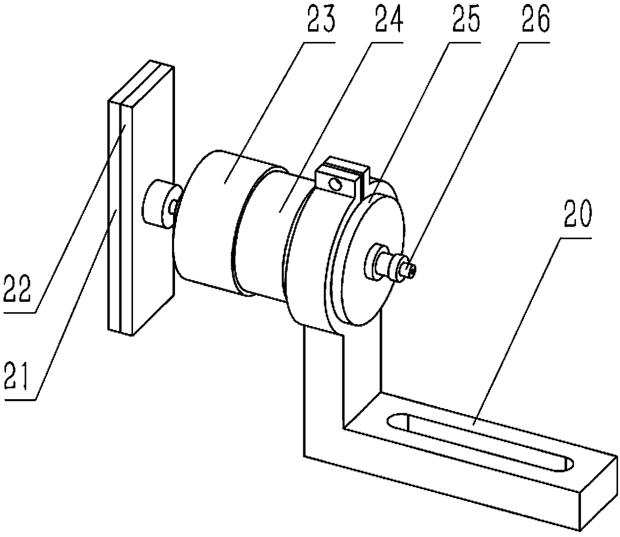
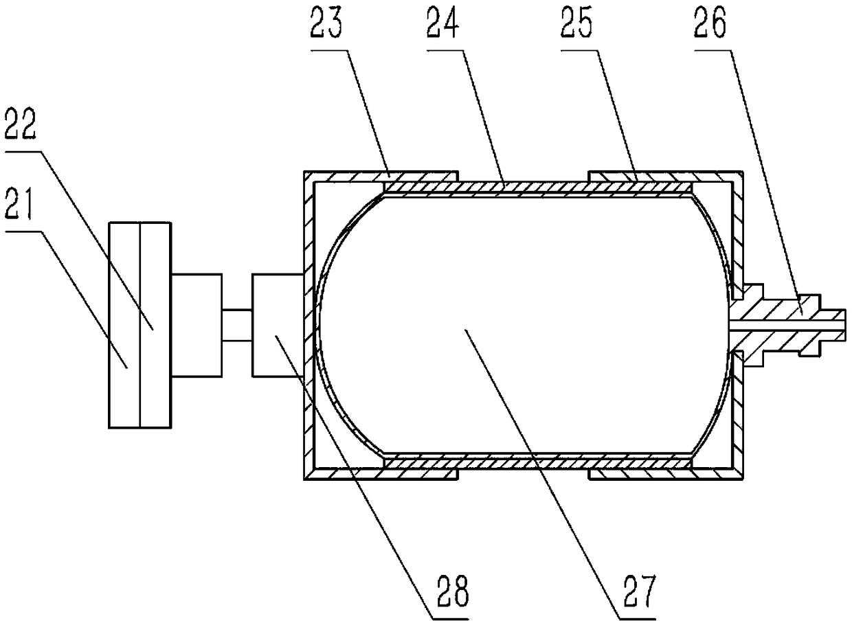
[0022] refer to Figure 1 ~ Figure 4 , the present embodiment is used for testing the deformation parameter of the deformed wing, which is composed of a test bench 1, an aerodynamic load loading device 19, a wing deformation driving force measuring device, an upper and lower skin deformation parameter measuring device, and a wing clamping assembly; Among them, the test bench 1 provides support and positioning for each component, and a number of screw holes are arranged at equal intervals horizontally and vertically on the test bench 1 for positioning and fixing each component. The wing clamping assembly includes a positioning fixture, a support, and the positioning fixture is connected to the support. The bolt is fixed on the test bench by cooperating with the screw hole of the test bench 1. The bolt is located in the normal direction of the bench plane, and the wing is tested. 2 is...


PUM


Abstract

The invention discloses a deformation parameter testing test bench for a deformation wing. According to the test bench, a digital infrared distance measurement sensor is utilized for non-contact distance measurement, the displacement values of different positions of the deformation wing are measured and input into a computer, and software is utilized for interpolation to obtain a deformation curveof the test wing; a workpiece is not in contact in the measurement process, and the surface of the workpiece cannot be scratched. Driving force for driving the deformation of the wing is measured bya micro force sensor, an inflatable airbag is utilized for loading aerodynamic load on the deformation wing, feedback is given to a controller, a closed-loop adjusting system is formed to control theapplication of the aerodynamic load, the application process of the aerodynamic load is effectively simulated, and distributed loading is achieved. The test bench is simple in layout structure, shortin measurement time, convenient to operate, assemble, disassemble, detect and maintain and low in cost. By means of the test bench, the measurement time can be effectively shortened, and the measurement efficiency is improved; the test bench has good applicability to tests of small and medium deformation wings.

Description

technical field [0001] The invention relates to the technical field of aviation equipment testing, in particular to a test platform for measuring deformation parameters of deformed wings, and is especially suitable for measuring the displacement and stress deformation parameters of the leading and trailing edges of large deformed wings. Background technique [0002] The wings are one of the few important parts that can adjust their attitude in flight. According to the working condition of the aircraft, changing the shape of the wing during flight can effectively increase the working efficiency of the wing. Among them, the effect of changing the camber of the wing is particularly prominent. In recent years, the rapid development of compliant mechanism technology has promoted the transformation of the original bulky, complex and inefficient traditional mechanical mechanism into a simple and robust deformation device, which has brought the development of variable camber wings ...

Claims


Application Information

Patent Timeline
Patent Type & Authority Applications(China)
IPC IPC(8): B64F5/60
CPCB64F5/60
Inventor 葛文杰张子昂张亚青周蓉易李玉柱
Owner NORTHWESTERN POLYTECHNICAL UNIV
Learn More