
Micro centrifuge

A centrifuge and micro technology, applied in the field of laboratory equipment, can solve the problems of reading errors and inconvenience in reading centrifuge test tubes, and achieve the effects of preventing errors, uniform force and simple operation.

Active Publication Date: 2019-03-22
THE SECOND AFFILIATED HOSPITAL ARMY MEDICAL UNIV
View PDF6 Cites 6 Cited by
  • Summary
  • Abstract
  • Description
  • Claims
  • Application Information

AI Technical Summary

Problems solved by technology

Because the centrifuge test tube is inclined, when the medical staff reads the scale of the centrifuge test tube, the head needs to be sideways for a certain distance, which brings inconvenience to the medical staff to read the scale of the centrifuge test tube, and when the medical staff reads the scale, due to the centrifuge test tube Inclined, prone to reading errors

Method used


Image

  • Micro centrifuge
  • Micro centrifuge
  • Micro centrifuge

Examples


Embodiment Construction

[0024] The following is further described in detail through specific implementation methods:

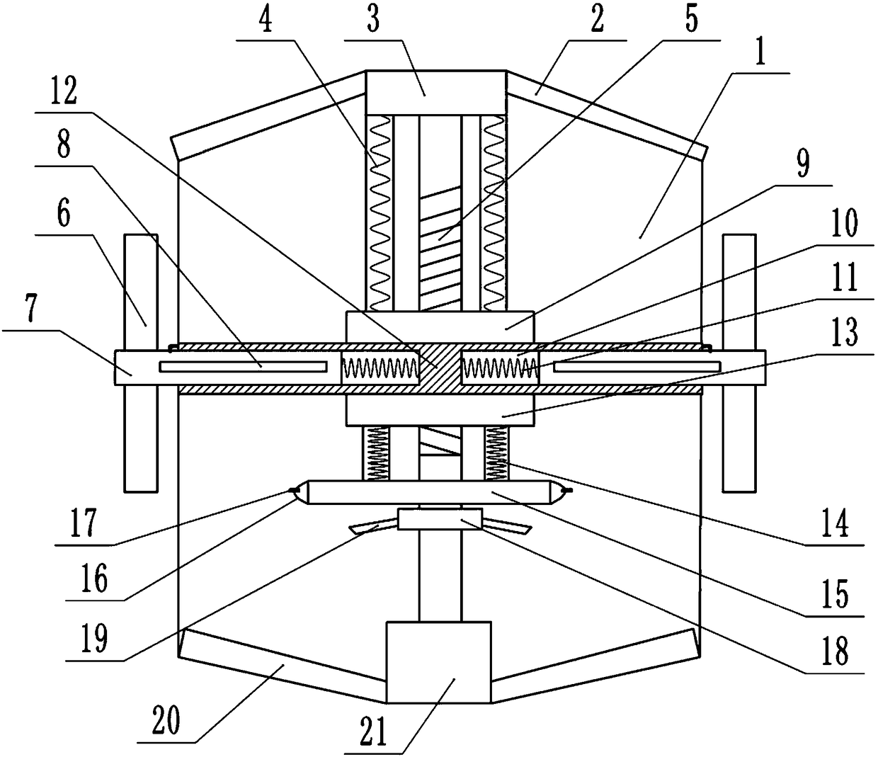
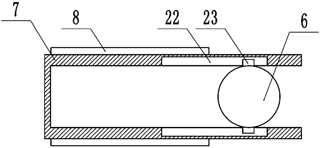
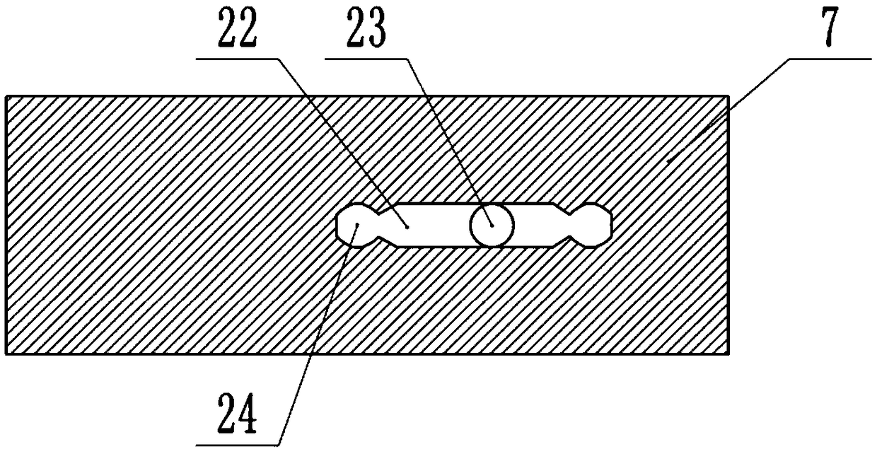
[0025] The reference signs in the drawings of the specification include: housing 1, upper cover 2, fixed block 3, upper compression spring 4, rotating shaft 5, test tube 6, carriage 7, sliding bar 8, first magnet 9, sliding cavity 10, Extension spring 11, turntable 12, second magnet 13, lower pressure spring 14, blast shell 15, elastic layer 16, pressure valve 17, blower fan 18, fan blade 19, lower cover 20, motor 21, chute 22, round Block 23, rotating groove 24.

[0026] The embodiment is basically as attached Figure 1-Figure 4 As shown: a microcentrifuge, including a housing 1, an upper cover 2 and a lower cover 20 are integrally formed on the housing 1, a fixed block 3 is integrally formed on the upper cover 2, a battery and a motor 21 are installed on the lower cover 20, and the battery Used to supply power to the motor 21 , the outer side of the casing 1 is provided with a wa...


PUM


Abstract

The invention relates to the field of laboratory equipment, in particular to a micro centrifuge. The micro centrifuge includes a rotating shaft and a motor for driving the rotating shaft to rotate, wherein a turntable is fixedly connected with the rotating shaft; the turntable is fixedly connected with the middle of the rotating shaft; a rotating test tube is arranged on the turntable; the upper side and the lower side of the turntable are correspondingly provided with a first magnet and a second magnet that are connected with the rotating shaft in a thread mode; the first magnet and the second magnet move in opposite directions; reset members are connected with the first magnet and the second magnet; a first magnetic strip and a second magnetic strip are correspondingly arranged on the upper end and the lower end of the test tube; the first magnet and the first magnetic strip are attracted to each other; and the second magnet and the second magnetic strip repel each other. According to the micro centrifuge, it is convenient for medical staff to read the scale on the test tube, so that reading errors are reduced.

Description

technical field [0001] The invention relates to the field of laboratory equipment, in particular to a microcentrifuge. Background technique [0002] When blood is tested, it is necessary to separate the blood. At present, the separation of blood components is generally carried out in a centrifuge. Existing blood centrifuges usually include a turntable on which inclined centrifuge test tubes are arranged. By making the motor drive the turntable to rotate, the turntable drives the inclined centrifuge test tubes to rotate, thereby achieving the purpose of centrifugation. Because the centrifuge test tube is inclined, when the medical staff reads the scale of the centrifuge test tube, the head needs to be sideways for a certain distance, which brings inconvenience to the medical staff to read the scale of the centrifuge test tube, and when the medical staff reads the scale, due to the centrifuge test tube Inclined, prone to reading errors. Contents of the invention [0003] T...

Claims


Application Information

Patent Timeline
Patent Type & Authority Applications(China)
IPC IPC(8): B04B5/04B04B7/00
CPCB04B5/0414B04B7/00
Inventor 俸蔚王亚兰杜春兰李韩
Owner THE SECOND AFFILIATED HOSPITAL ARMY MEDICAL UNIV
Learn More