
Floor spherical lamp

A technology for spherical lamps and floors, applied in the direction of lampshades, damage prevention measures for lighting devices, cooling/heating devices for lighting devices, etc., can solve the problems of inability to move the position, poor decoration effect, poor interaction effect of people, etc., and achieve structural design Novel and interactive effects

Inactive Publication Date: 2019-03-19
俞天舜
View PDF9 Cites 0 Cited by
  • Summary
  • Abstract
  • Description
  • Claims
  • Application Information

AI Technical Summary

Problems solved by technology

[0002] Every family room will use more LED lighting fixtures. LED lighting fixtures are generally installed on the ceiling, and the number of lamps installed will definitely not be too much, resulting in poor lighting in many indoor areas. The lighting effect in some areas is poor, and the lamps installed on the floor are generally fixed structures, resulting in the position cannot be moved, the decorative effect is poor, the interaction effect with people is poor, the position of the floor lamps cannot be adjusted, and the decorative effect is poor

Method used


Image

  • Floor spherical lamp
  • Floor spherical lamp
  • Floor spherical lamp

Examples


Embodiment Construction

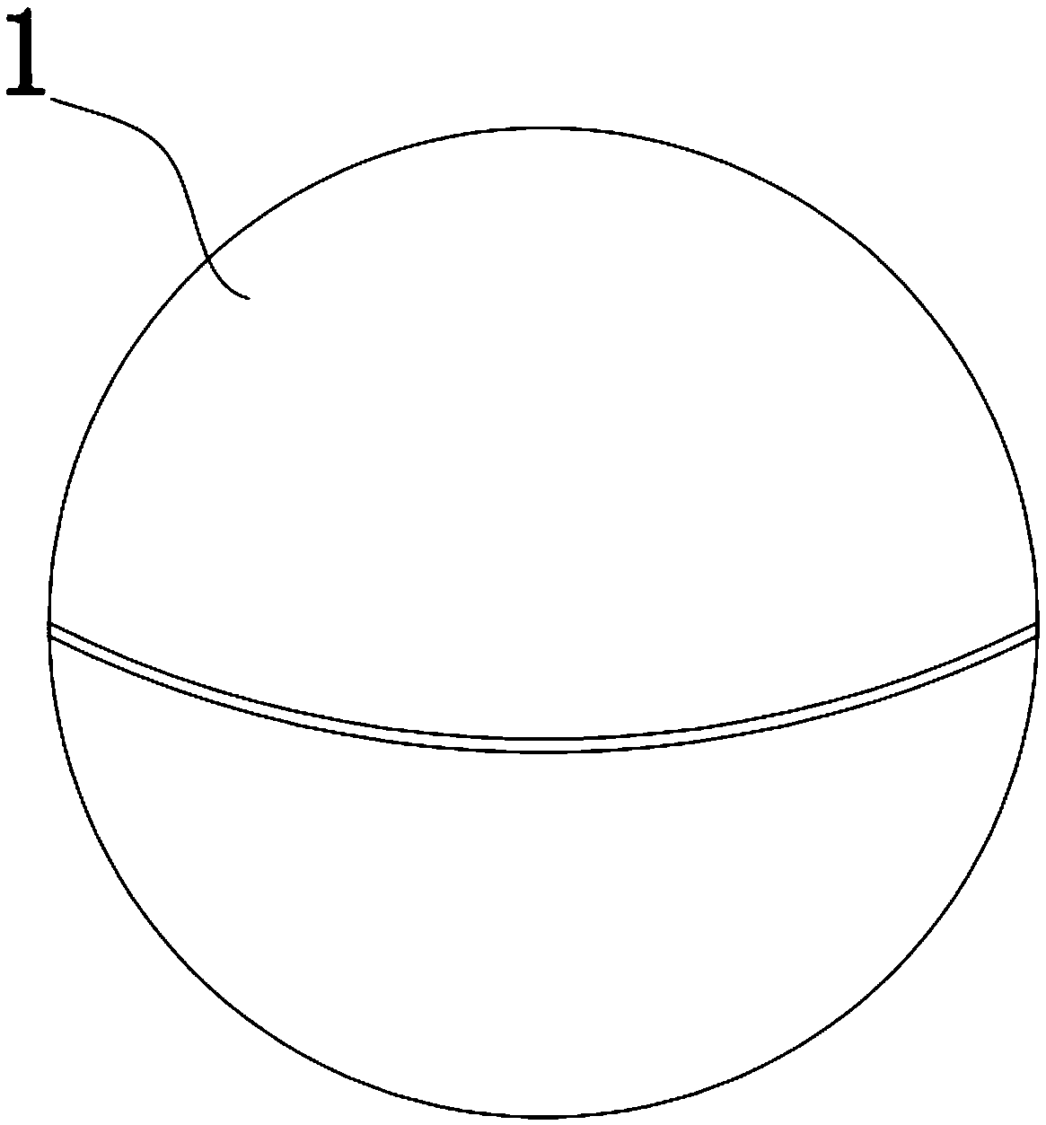
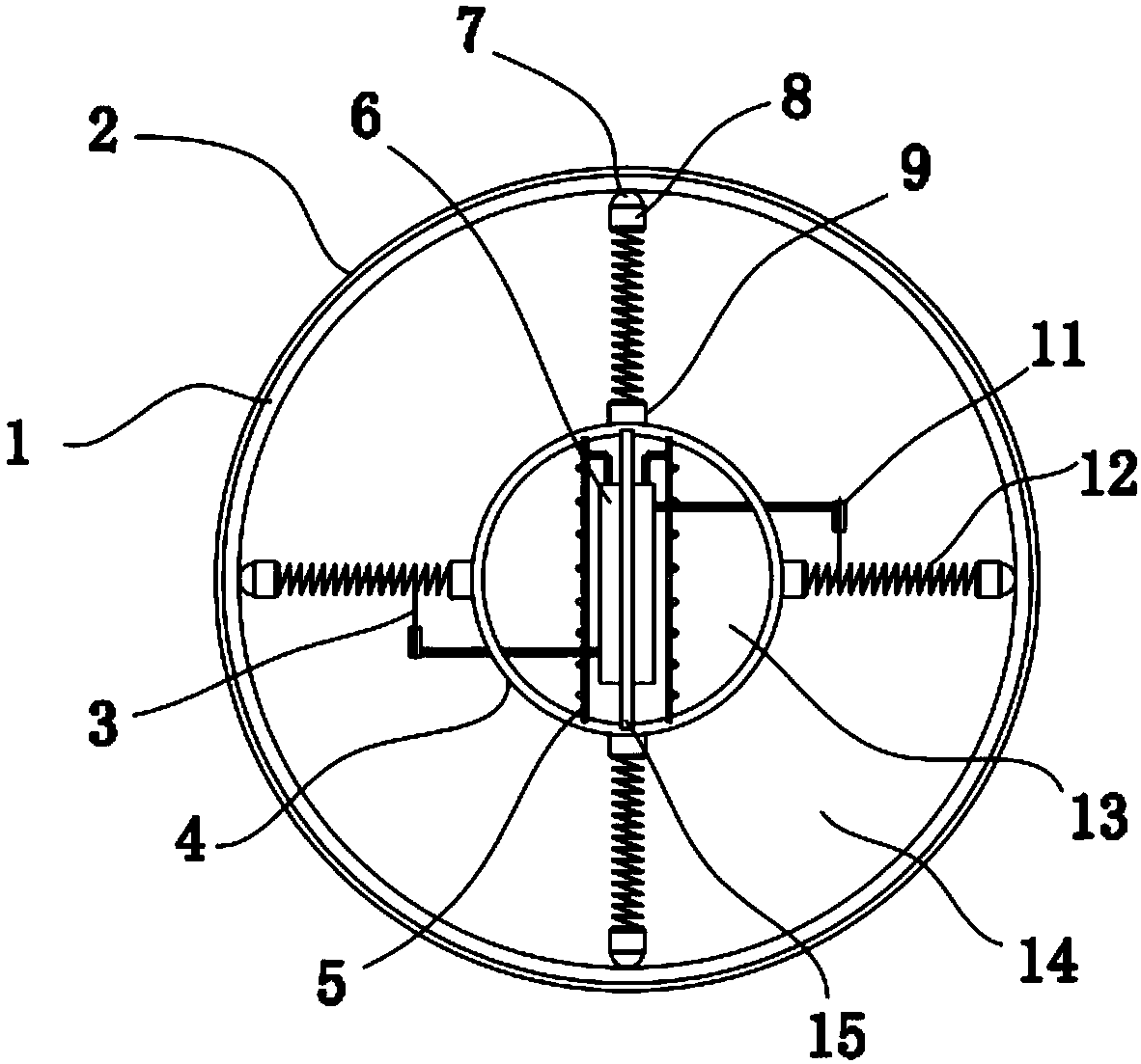
[0014] Such as figure 1 and figure 2 As shown, the local floor spherical lamp includes a spherical housing 1 composed of two hemispheres threaded. A light-emitting component is provided;

[0015] The luminous ball 4 is suspended in the spherical cavity 14 through an elastic support structure on the front, rear, left, right, upper, and lower sides respectively;

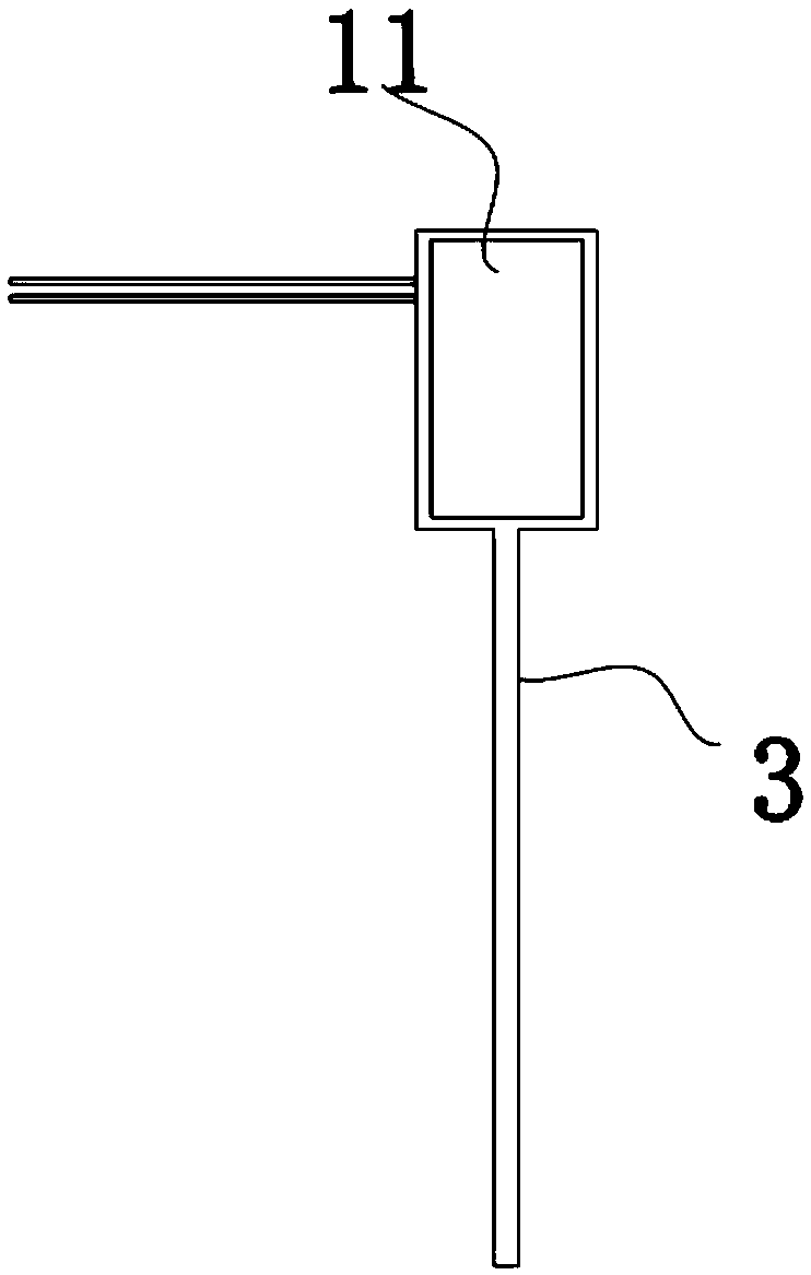
[0016] A micro-vibration generator 11 is arranged on the elastic support structure, and the micro-vibration generator 11 charges the charging module in the luminous ball. touch.

[0017] In this embodiment, the elastic support structure includes a connecting part 9 and a connecting spring 12, the rolling structure includes a ball 7 and a ball bushing 8, the connecting part 9 and the luminous ball 4 are integrally injection molded, and the bottom of the connecting spring 12 and the connecting part 9 Bonding and fixing, the other end of the connection spring 12 is fixedly bonded to the end surface of the ball bushin...


PUM


Abstract

The invention discloses a floor spherical lamp which comprises a spherical shell composed of two hemispheres by screw assembly. The middle of the spherical shell is provided with a spherical cavity, alight emitting ball is suspended in the spherical cavity, a light emitting assembly is arranged in the light emitting ball, the light emitting ball is suspended in the spherical cavity through elastic supporting structures on the front, back, left, right, upper and lower faces of the light emitting ball, minitype vibration power generators are arranged on the elastic supporting structures and charge charging modules in the light emitting ball, the sides, opposite to the spherical cavity, of the elastic supporting structures are provided with rolling structures, and the elastic supporting structures make rolling contact with the inner wall of the spherical cavity. The spherical lamp is mainly placed on planes such as a floor and other bottom face places, can be arbitrarily rolled on the ground during use, can be effectively rolled to any position for illumination, has the principle of self power generation, has quite good interaction, is novel in structural design and does not limitedby regions.

Description

technical field [0001] The invention relates to the field of LED lamps, in particular to a floor spherical lamp. Background technique [0002] Every family room will use more LED lighting fixtures. LED lighting fixtures are generally installed on the ceiling, and the number of lamps installed will definitely not be too much, resulting in poor lighting in many indoor areas. The lighting effect in some areas is poor, and the lamps and lanterns installed on the floor are generally fixed structures, resulting in immobile positions, poor decorative effects, poor interaction with people, and inability to adjust the positions of floor lamps, resulting in poor decorative effects. Contents of the invention [0003] The technical problem to be solved by the present invention is to provide a floor spherical lamp, which can roll freely on the ground when in use, can effectively roll to any position for lighting, and has the principle of self-power generation, has very good interaction...

Claims


Application Information

Patent Timeline
IPC IPC(8): F21S9/02F21S9/04F21V3/02F21V15/02F21V19/00F21V29/83F21Y115/10
CPCF21S9/02F21S9/04F21V3/02F21V15/02F21V19/001F21V29/83F21Y2115/10
Inventor 俞天舜
Owner 俞天舜
Learn More