Circuit board feeding device

A circuit board and conveying device technology, which is applied in the directions of transportation and packaging, conveyors, conveyor objects, etc., can solve the problems of large space occupation, increased maintenance costs, and high costs, and achieves improved feeding accuracy, small space occupation, and high cost. simple structure

Pending Publication Date: 2019-03-19
DONGGUAN WORLD PRECISION MACHINERY
View PDF10 Cites 4 Cited by
  • Summary
  • Abstract
  • Description
  • Claims
  • Application Information

AI Technical Summary

Problems solved by technology

[0003] For the loading of circuit boards, two layers of linear conveyor belts with superimposed placement and opposite transmission directions are often set up, and lifting platforms for switching carriers are set on both sides of the linear conveyor belt. However, this loading device is not only structural It is complex, takes up a lot of space and costs high, and the carrier must be switched between two layers of linear conveyor belts. In other words, the carrier cannot be fixed on the linear conveyor belt, regardless of the manual placement of the carrier. The position deviation, or the position deviation generated when the carrier is transported on the linear conveyor belt, will directly affect the position accuracy of the circuit board in the carrier at the loading station, thereby indirectly affecting the assembly accuracy of the subsequent circuit board; At the same time, the positional deviation of the carrier is likely to cause collision between the clamping device and the carrier when it is extended into the carrier, which will increase the overall maintenance cost, so the existing feeding device cannot meet the existing requirements. Production needs

Method used


Image

  • Circuit board feeding device
  • Circuit board feeding device
  • Circuit board feeding device

Examples


Embodiment Construction

[0022] In order to describe the technical content and structural features of the present invention in detail, further description will be given below in conjunction with the implementation and accompanying drawings.

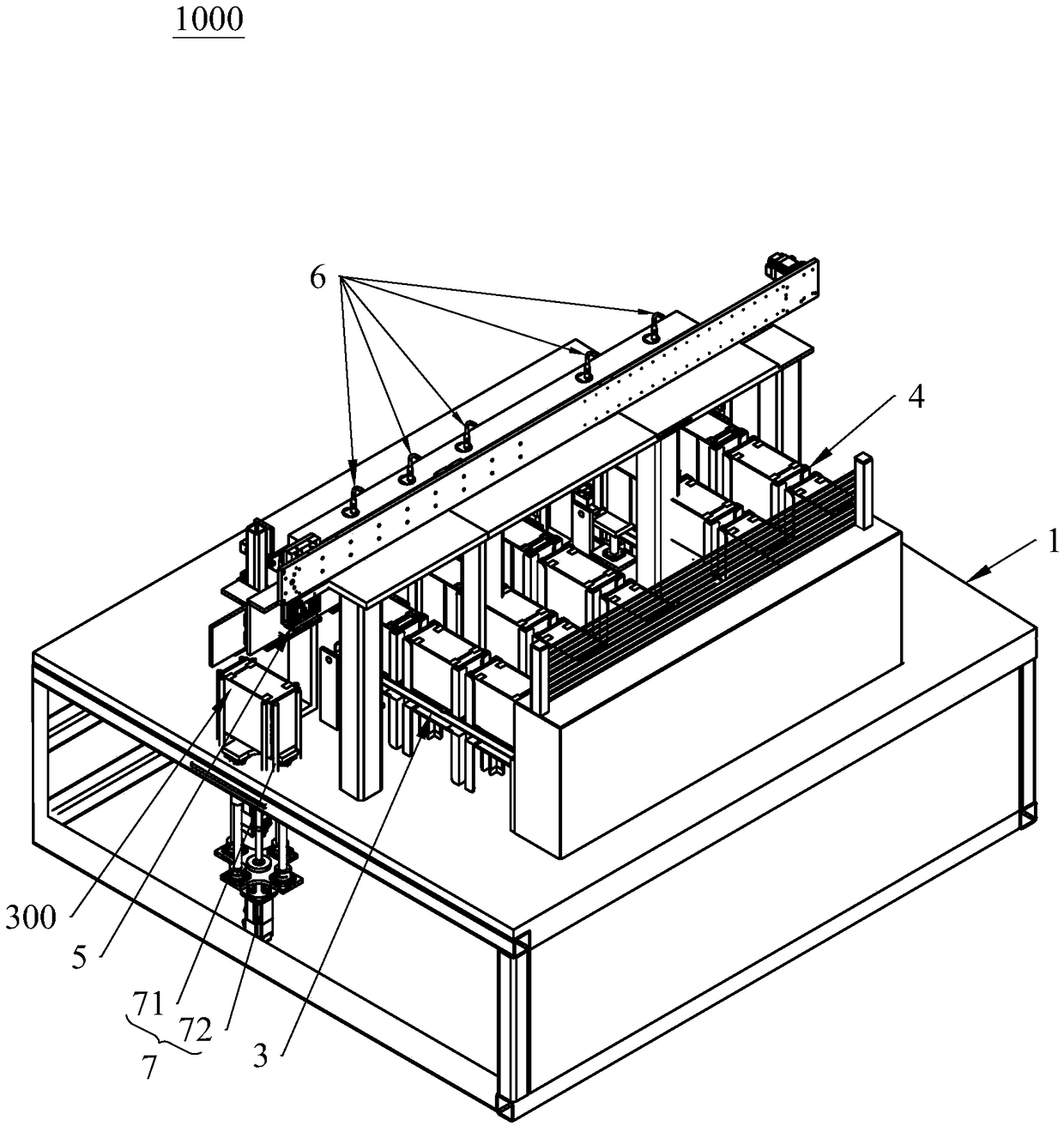
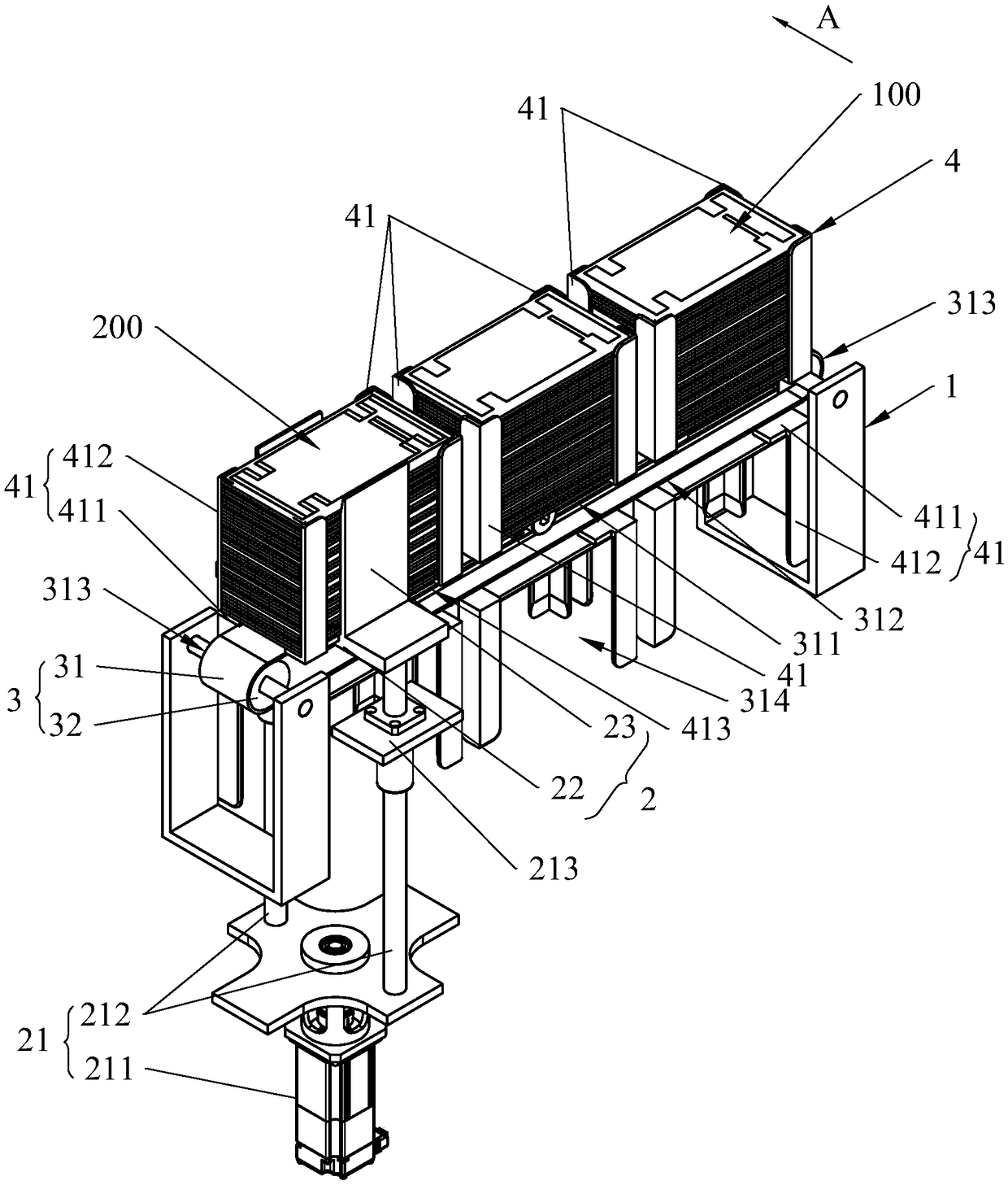
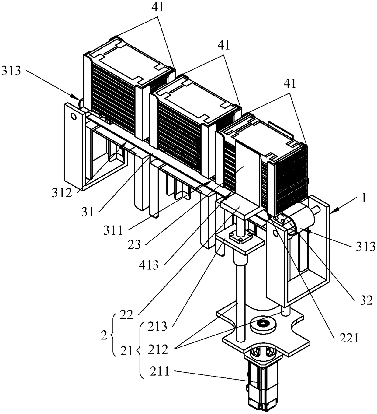
[0023] see Figure 1 to Figure 2 , the circuit board feeding device 1000 of the present invention is suitable for being electrically connected with an external controller (not shown in the figure), and the circuit board feeding device 1000 includes a frame 1 and a transfer manipulator 5, a top The lifting mechanism 2, the conveying device 3 and the limit frame 4 used to limit the stacked circuit boards, the conveying device 3 has a transmission part 31 that can perform rotary motion, and the limit frame 4 is fixed on the transmission part 31, Preferably, there are at least two limit frames 4, and all limit frames 4 are spaced and fixed on the transmission member 31, and the interval between two adjacent limit frames 4 is equal; the two ends of the transmission me...


PUM


Abstract

The invention discloses a circuit board feeding device. The circuit board feeding device comprises a machine frame, a jacking mechanism arranged on the machine frame, a conveying device and a limitingframe used for limiting the circuit board stacked in the stacking mode, the conveying device is provided with a conveying part capable of carrying out rotary motion, the limiting frame is fixed on the conveying part, the two ends of the conveying part are provided with a discharging station and a feeding station respectively, the conveying part can convey the limiting frame fully loaded at the discharging station to the feeding station, and the limiting frame at the loading station is conveyed to the discharging station; the two sides of the limiting frame in the width direction of the conveying part are provided with notches, the output end of the jacking mechanism is provided with a bearing part, the bearing part extends into the limiting frame through the notches, so that the edge of the circuit board is borne on the bearing part and abuts against all the circuit boards to rise. According to the circuit board feeding device, the circuit board can be accurately positioned, the circuit board can be accurately conveyed to the feeding station, the feeding accuracy of the circuit board can be improved, and the circuit board feeding device has the advantages of being simple in structure, small in occupied space and the like.

Description

technical field [0001] The invention relates to the field of photovoltaic power generation, in particular to a circuit board feeding device for a substring circuit board in a solar photovoltaic panel battery. Background technique [0002] Photovoltaic power generation is based on the principle of photovoltaic effect, using solar cells to directly convert sunlight energy into electrical energy. Regardless of whether it is used independently or connected to the grid for power generation, the photovoltaic power generation system is mainly composed of three parts: solar panels (components), controllers and inverters. In order to achieve the maximum output power, solar panels are mostly constructed by connecting multiple circuit boards in series, and the welding between the two circuit boards is usually realized by welding bridge copper sheets between the circuit boards. [0003] For the loading of circuit boards, two layers of linear conveyor belts with superimposed placement a...

Claims


Application Information

Patent Timeline
Patent Type & Authority Applications(China)
IPC IPC(8): B65G47/90B65G47/74
CPCB65G47/74B65G47/90B65G2201/022
Inventor 陈灿华赵子春吴锐宇杨波
Owner DONGGUAN WORLD PRECISION MACHINERY
Why Eureka
Try Eureka