
A mounter clamping mechanism

A technology of clamping mechanism and placement machine, which is applied to the manufacturing of printed circuits, electrical components, printed circuits, etc. Stable, increased flexibility, easy to operate

Active Publication Date: 2021-09-21
惠州市子阳光电照明有限公司
View PDF6 Cites 0 Cited by
  • Summary
  • Abstract
  • Description
  • Claims
  • Application Information

AI Technical Summary

Problems solved by technology

[0004] The purpose of the present invention is to provide a clamping mechanism of a chip mounter, which has the advantage of being convenient to use, and solves the problem that the traditional clamping mechanism is inconvenient to use. When clamping an object to be processed, a lot of time is often wasted, and The clamping process is cumbersome, which greatly reduces the working efficiency of the staff

Method used


Image

  • A mounter clamping mechanism
  • A mounter clamping mechanism
  • A mounter clamping mechanism

Examples


Embodiment Construction

[0022] The following will clearly and completely describe the technical solutions in the embodiments of the present invention with reference to the accompanying drawings in the embodiments of the present invention. Obviously, the described embodiments are only some, not all, embodiments of the present invention. Based on the embodiments of the present invention, all other embodiments obtained by persons of ordinary skill in the art without making creative efforts belong to the protection scope of the present invention.

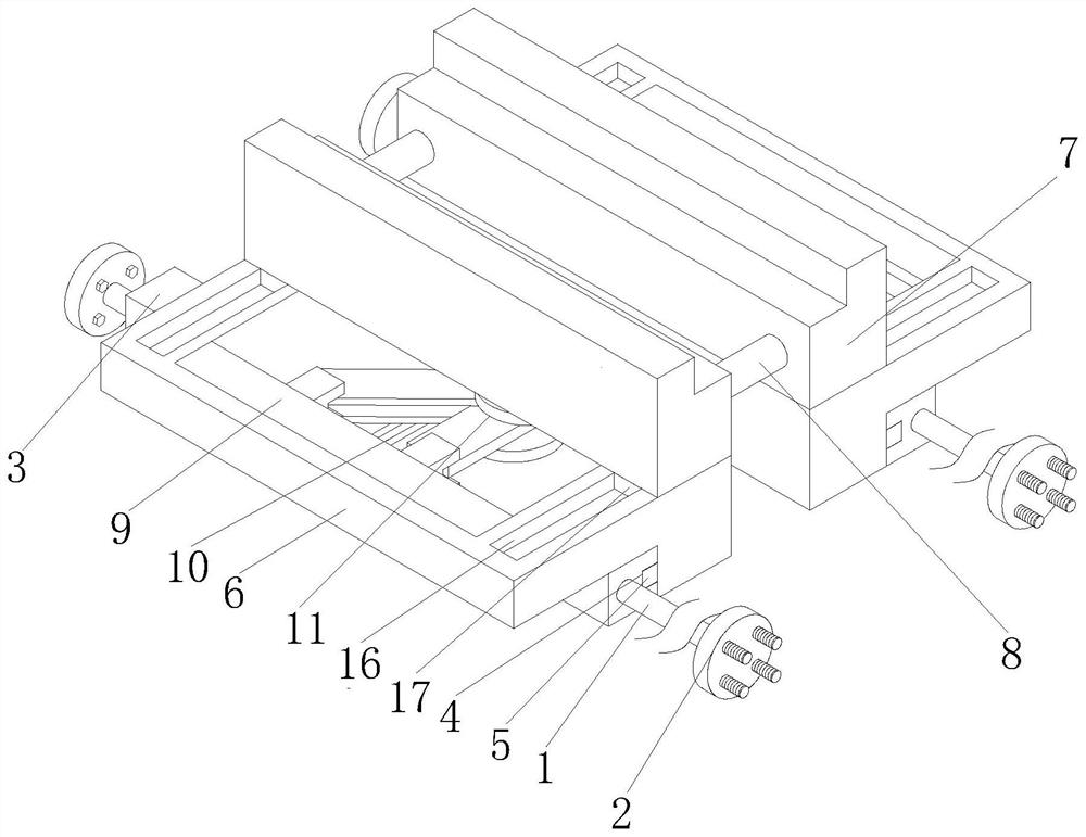
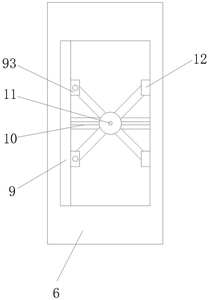
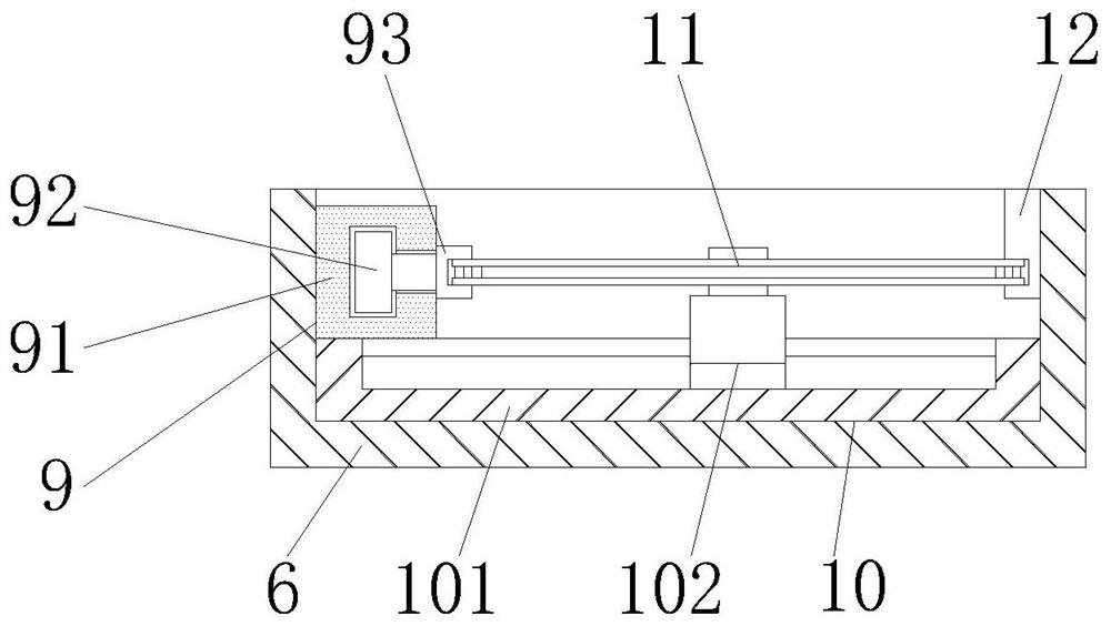
[0023] see Figure 1-6 , the present invention provides a technical solution: a chip mounter clamping mechanism, including a moving pole 1, the number of the moving pole 1 is two, and both ends of the moving pole 1 are fixedly connected with a fixing part 2, and the moving The surface of the support rod 1 is covered with a moving sliding sleeve 3, and the opposite sides of the two moving sliding sleeves 3 are provided with a chute 4, and the inner cavity of th...


PUM


Abstract

The invention discloses a clamping mechanism of a placement machine, which includes a moving support rod. There are moving sliding sleeves, the opposite sides of the two moving sliding sleeves are provided with chute, the inner cavity of the chute is slidably connected with the slider, the top of the moving sliding sleeve is provided with a clamping movable frame, the One side of the clamping movable frame close to the slider is fixedly connected with the slider, and the top of the clamping movable frame is movably connected with a clamping block. The present invention uses clamping block, sliding rod, guiding slide rail, supporting limit slide rail, movable chamber, moving plate, spring, baffle plate, rotating shaft, first pole and second pole to make the staff It is more time-saving and labor-saving when placing the processed items, which makes the operation of the processed items easier and more convenient for users to use during the clamping process.

Description

technical field [0001] The invention relates to the technical field of placement machines, in particular to a clamping mechanism of a placement machine. Background technique [0002] Mounter, also known as "mounter", "surface mount system", in the production line, it is configured after the dispenser or screen printing machine, it is to place the surface mount components accurately by moving the placement head A kind of equipment on the PCB pad, which is divided into two types: manual and fully automatic. It is used to realize high-speed and high-precision placement of components. It is the most critical and complex equipment in the entire SMI and production. The placement machine is the SMT equipment used in the production of SMT. Now, the placement machine has developed from the early low-speed mechanical placement machine to the high-speed optical centering placement machine, and is modularized to multi-function and flexible connection. develop. [0003] In the work of ...

Claims


Application Information

Patent Timeline
Patent Type & Authority Patents(China)
IPC IPC(8): H05K3/34H05K13/04
CPCH05K3/341H05K13/0465
Inventor 赵绍波郭瑞占
Owner 惠州市子阳光电照明有限公司
Learn More