
Full high-definition digital image transmission device for ultra-long distance

A technology of digital image and transmission device, applied in the direction of shock absorber, spring/shock absorber, shock absorber, etc., can solve the problems of poor signal quality, inability to adjust height and angle, unstable transmission, etc., and achieve transmission delay The effect of short, stable image transmission and high signal reception strength

Pending Publication Date: 2019-03-15
浙江云来集科技有限公司
View PDF0 Cites 1 Cited by
  • Summary
  • Abstract
  • Description
  • Claims
  • Application Information

AI Technical Summary

Problems solved by technology

[0006] Aiming at the deficiencies of the prior art, the present invention provides a full high-definition digital image transmission device for ultra-long distance, which solves the problem that the existing full high-definition digital image transmission device for ultra-long distance cannot adjust the height and angle, and the signal The problem of poor quality and unstable transmission

Method used


Image

  • Full high-definition digital image transmission device for ultra-long distance
  • Full high-definition digital image transmission device for ultra-long distance
  • Full high-definition digital image transmission device for ultra-long distance

Examples


Embodiment Construction

[0029] The following will clearly and completely describe the technical solutions in the embodiments of the present invention with reference to the accompanying drawings in the embodiments of the present invention. Obviously, the described embodiments are only some, not all, embodiments of the present invention.

[0030] In describing the present invention, it should be understood that the terms "center", "longitudinal", "transverse", "length", "width", "thickness", "upper", "lower", "front", " Back", "Left", "Right", "Vertical", "Horizontal", "Top", "Bottom", "Inner", "Outer", "Clockwise", "Counterclockwise", "Axial", The orientation or positional relationship indicated by "radial", "circumferential", etc. is based on the orientation or positional relationship shown in the drawings, and is only for the convenience of describing the present invention and simplifying the description, rather than indicating or implying the referred device or element Must be in a particular orien...


PUM


Abstract

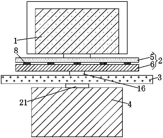
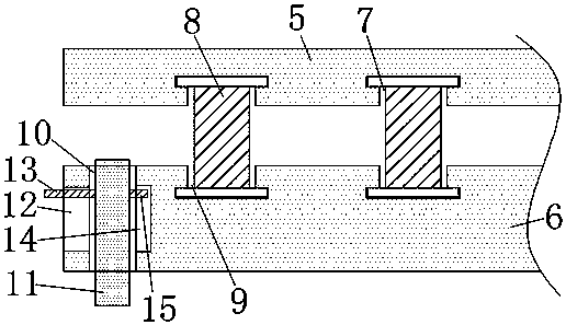
The invention discloses a full high-definition digital image transmission device for an ultra-long distance, and relates to the technical field of digital signal transmission. The full high-definitiondigital image transmission device for the ultra-long distance comprises a transmission device, a bearing plate, a supporting plate and a lifting device. The bearing plate comprises a first connectingplate and a second connecting plate, the lower surface of the transmission device is fixedly connected with the upper surface of the first connecting plate, a plurality of first grooves are formed inthe lower surface of the first connecting plate, and supporting springs are fixedly connected with the inner parts of the first grooves. According to the full high-definition digital image transmission device for the ultra-long distance, the bearing plate is composed of the first connecting plate and the second connecting plate, the transmission device has a shock absorbing effect due to the supporting springs, so that the transmission device transmit more stably, the bearing plate can rotate at the top of the supporting plate through a connecting column and a rotating plate, thereby facilitating the adjustment of the direction of the transmission device and the receiving and transmission of signals.

Description

technical field [0001] The invention relates to the technical field of digital signal transmission, in particular to an ultra-long-distance full high-definition digital image transmission device. Background technique [0002] Image transmission, that is, real-time video transmission, mainly has two concepts. One is mobile transmission, that is, mobile communication, and the other is broadband transmission, that is, broadband communication. In the past, wireless image transmission was mainly based on one-way analog TV broadcasting services. . [0003] An image can be defined as the reproduction of a scene on a certain medium, such as pictures, movies, faxes, televisions, and other media that allow people to obtain image information, and the process of transmitting image information to a distant place or storing image information is collectively referred to as image transmission. [0004] The current image transmission equipment is generally one-piece structure, which cannot ...

Claims


Application Information

Patent Timeline
Patent Type & Authority Applications(China)
IPC IPC(8): F16M11/24F16F7/00
CPCF16F7/00F16M11/24
Inventor 孟祥宇
Owner 浙江云来集科技有限公司
Learn More