
Anti-collision device for laser-guided vehicle and implementation method

A technology of laser guidance and anti-collision device, which is applied in two-dimensional position/channel control, vehicle position/route/height control, vehicle components and other directions, which can solve the problem of affecting the efficiency of transportation, delaying the process of transportation, hindering the car, etc. problem, to achieve good anti-collision effect, avoid continued collision, and improve the effect of handling efficiency

Active Publication Date: 2019-03-15
TIANJIN SAIXIANG M&E ENG CO LTD
View PDF12 Cites 3 Cited by
  • Summary
  • Abstract
  • Description
  • Claims
  • Application Information

AI Technical Summary

Problems solved by technology

[0007] (1) The existing laser-guided car usually stops working after hitting an obstacle. Although it can avoid damage to the car body, it needs to be restarted and the route can be changed before continuing to work, which affects the efficiency of handling;
[0008] (2) When the laser-guided trolley is carrying goods, usually multiple trolleys work together and walk according to the predetermined route. When one of the trolleys hits an obstacle, it will inevitably affect and hinder other trolleys, thus delaying the handling. process;
[0009] (3) Most of the existing laser-guided cars only use mechanical buffering to avoid damage to the car body. The anti-collision effect is not ideal, and it cannot effectively prevent the car body from hitting obstacles

Method used


Image

  • Anti-collision device for laser-guided vehicle and implementation method
  • Anti-collision device for laser-guided vehicle and implementation method
  • Anti-collision device for laser-guided vehicle and implementation method

Examples


Embodiment Construction

[0040] The following will clearly and completely describe the technical solutions in the embodiments of the present invention with reference to the accompanying drawings in the embodiments of the present invention. Obviously, the described embodiments are only some, not all, embodiments of the present invention. Based on the embodiments of the present invention, all other embodiments obtained by persons of ordinary skill in the art without making creative efforts belong to the protection scope of the present invention.

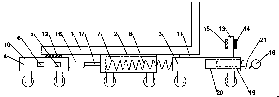
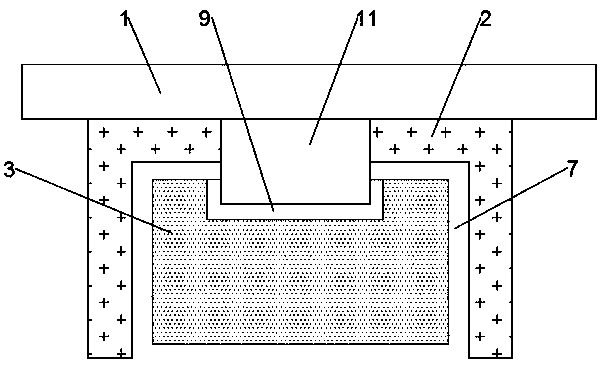
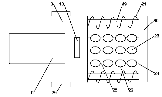
[0041] Such as Figure 1 to Figure 3 As shown, the present invention provides a kind of anti-collision device of laser guided trolley, comprises car body 1, and car body 1 is used for placing the goods transported, and car body 1 is narrower than common laser guided trolley, and car body 1 The center of the bottom end of the body 1 is fixedly connected with a central moving part 2, and the front and rear sides of the central moving part 2 are respectively prov...


PUM


Abstract

The invention discloses an anti-collision device for a laser-guided vehicle and an implementation method. The device includes a vehicle body. The bottom of the vehicle body is fixedly connected with acentral moving part, the front and rear sides of the central moving part are provided with a front moving part and a rear moving part respectively, the rear driving part is internally provided with adrive mechanism and a control mechanism, the bottom of the side face of the central moving part is provided with an arch groove, the side face of the arch groove is connected with the front moving part through a cushion spring, the tops of the front moving part and the rear moving part are provided with a front sliding rail and a rear sliding rail, and the front and rear sides of the bottom surface of the vehicle body are provided with a front guide slider and a rear guide slider. The device prevents vehicle collision through mechanical buffering and intelligent obstacle avoidance, the anti-collision effect is better, the vehicle does not need to work, and the carrying efficiency is easily improved. Meanwhile, the walking route of one vehicle can be changed when the front vehicle collidesor avoids obstacles, and the handling work of other vehicles is not affected.

Description

technical field [0001] The invention relates to the field of intelligent material handling, in particular to an anti-collision device and a realization method of a laser guided trolley. Background technique [0002] Automatic guided vehicle, also known as AGV, refers to automatic guidance equipment such as magnetic strips, rails or lasers, driving along a planned path, powered by batteries, and equipped with safety protection and various auxiliary mechanisms (such as transfer, Assembly mechanism) unmanned automated vehicles. Usually multiple AGVs and control computers (consoles), navigation equipment, charging equipment and peripheral auxiliary equipment form the AGV system. The main working principle is that under the monitoring and task scheduling of the control computer, the AGV can accurately follow the prescribed path. After arriving at the designated position of the task, a series of tasks are completed, and the control computer can decide whether to go to the chargin...

Claims


Application Information

Patent Timeline
Patent Type & Authority Applications(China)
IPC IPC(8): B60R19/36B60R19/38B60R21/0136G05D1/02
CPCB60R19/023B60R19/36B60R19/38B60R21/0136B60R2019/005B60R2019/007B60R2019/026G05D1/0242
Inventor 杨如凤
Owner TIANJIN SAIXIANG M&E ENG CO LTD
Learn More