Assembly pressing fixture and pressing method for vent screws and screw caps

A technology of exhaust screw and pressing fixture, which is applied in the direction of manufacturing tools, metal processing, metal processing equipment, etc., and can solve the problems of low manual assembly efficiency of exhaust screw and screw cap

Active Publication Date: 2019-03-15
重庆市璧山区昌瑞电子有限公司
View PDF8 Cites 0 Cited by
  • Summary
  • Abstract
  • Description
  • Claims
  • Application Information

AI Technical Summary

Problems solved by technology

[0004] In view of the above deficiencies in the prior art, the purpose of the present invention is to solve the problem of low manual assembly effi...

Method used


Image

  • Assembly pressing fixture and pressing method for vent screws and screw caps
  • Assembly pressing fixture and pressing method for vent screws and screw caps
  • Assembly pressing fixture and pressing method for vent screws and screw caps

Examples


Embodiment Construction

[0024] The technical solutions of the present invention will be clearly and completely described below in conjunction with the accompanying drawings. Obviously, the described embodiments are only preferred embodiments of the present invention, rather than all the embodiments. Based on the embodiments of the present invention, all other embodiments obtained by those of ordinary skill in the art without creative work shall fall within the protection scope of the present invention.

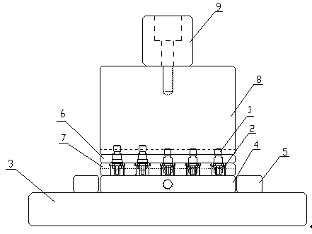
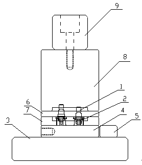
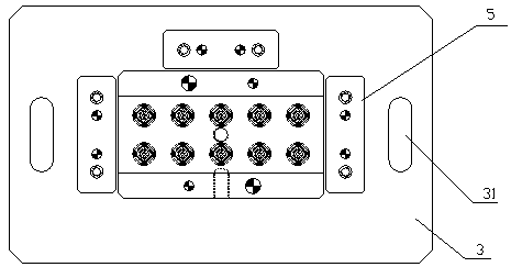
[0025] Such as Figure 1-3 As shown, an assembling and pressing jig for a vent screw and a screw cap includes a mold base 3 on which a lower backing plate 4 is provided, and the lower backing plate 4 is provided with screw plugs in a descending order The cap positioning plate 7 and the exhaust screw positioning plate 6. The screw cap positioning plate 7 is provided with 10 screw cap positioning holes 71, and the shape and size of the screw cap positioning holes 71 are consistent with the shape and size ...


PUM


Abstract

The invention discloses an assembly pressing fixture and a pressing method for vent screws and screw caps. The assembly pressing fixture comprises a mold base, wherein the mold base is provided with ascrew cap positioning plate and a vent screw positioning plate, the screw cap positioning plate is provided with a plurality of screw cap positioning holes, and the vent screw positioning plate, is provided with a plurality of vent screw positioning holes, and the screw cap positioning holes and the vent screw positioning holes are one-to-one corresponding; an upper pressing plate is arranged above the mold base, and the upper pressing plate is connected with a mold handle of a punching device. Compared with manual assembly, the use of the pressing fixture and the pressing method of the present invention can save labor, and at the same time, since a plurality of components can be assembled each time, the production efficiency is greatly improved.

Description

Technical field [0001] The invention relates to a vent screw assembly equipment, in particular to an assembling and pressing jig and a pressing method of a vent screw and a screw cap. Background technique [0002] The vent screw, as the name suggests, mainly plays the role of venting or venting. The common vent screw currently on the market includes a cylindrical body with an axial vent hole in the body and an external thread at the front end of the body. The rear part of the main body is provided with a radial exhaust hole communicating with the axial exhaust hole, and the rear part of the main body is sleeved with a screw plug cap, which is used to prevent dust from entering the exhaust screw. When the exhaust screw is in use, it is matched with a stepped hole with internal threads. When venting is not required, the exhaust screw is screwed into the stepped hole until a seal is formed on the internal step at the top of the exhaust screw. When the exhaust is required, loosen the...

Claims


Application Information

Patent Timeline
IPC IPC(8): B23P19/06
CPCB23P19/06
Inventor 罗燕陈国强龚家利
Owner 重庆市璧山区昌瑞电子有限公司
Why Eureka
Try Eureka