High-speed kerve cold forming machine

A cold forming machine and cold forming technology, which is applied to the driving device of metal rolling mill, metal rolling, manufacturing tools, etc., can solve the problems of unstable product quality and low equipment efficiency, and can overcome bending deformation, Smooth transmission

Pending Publication Date: 2019-03-15
GUANGDONG AURICAN HARDWARE TECH CO LTD
View PDF0 Cites 0 Cited by
  • Summary
  • Abstract
  • Description
  • Claims
  • Application Information

AI Technical Summary

Problems solved by technology

[0004] The purpose of the present invention is to provide a high-speed bottom trough cold forming machine to solve the technical problem of low equipment efficiency and unstable product quality in the prior art

Method used


Image

  • High-speed kerve cold forming machine
  • High-speed kerve cold forming machine
  • High-speed kerve cold forming machine

Examples


Embodiment Construction

[0097] In order to enable those skilled in the art to better understand the solution of the present invention, the present invention will be further described in detail below in conjunction with the accompanying drawings and specific embodiments.

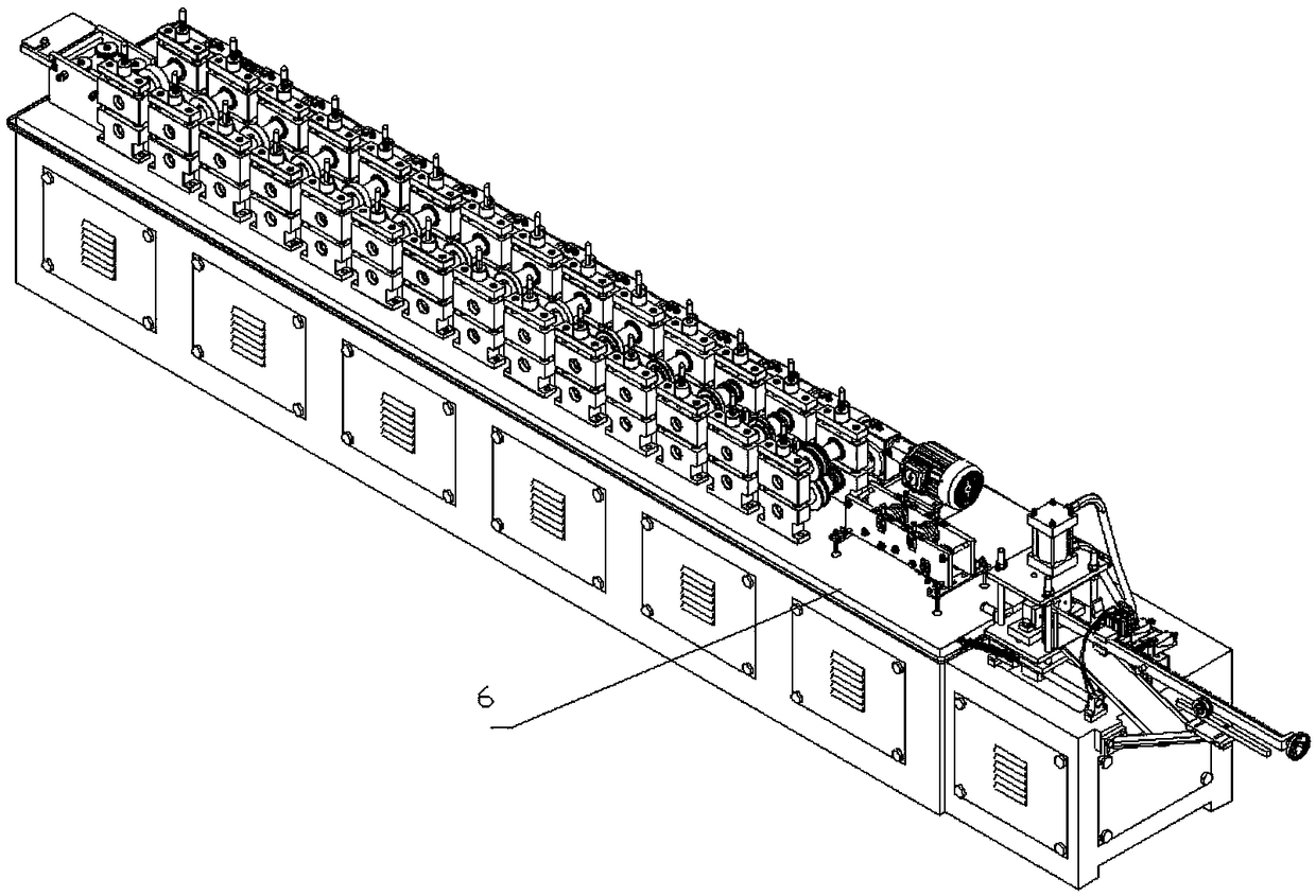
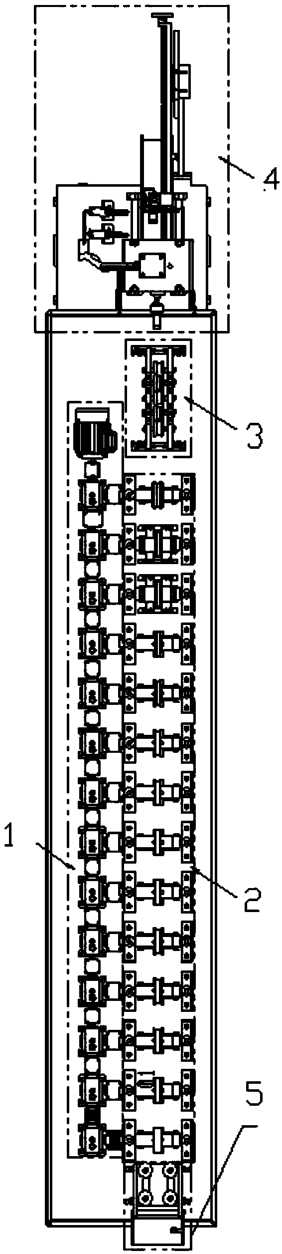
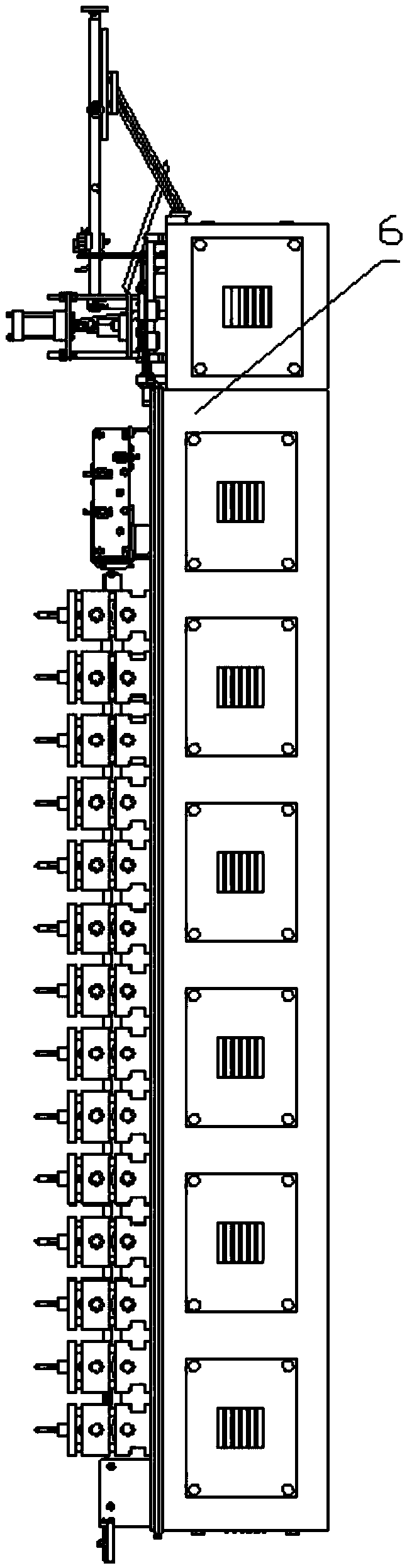
[0098] Please refer to Figure 1-37 , a kind of high-speed workpiece cold forming machine provided by the present invention comprises: power transmission mechanism 1, cold press forming mechanism 2, flattening mechanism 3, cutting mechanism 4 and cooling mechanism; Described power transmission mechanism 1 and described cold press forming mechanism 2; the cold press forming mechanism 2, leveling mechanism 3, cutting mechanism 4 and cooling mechanism are arranged in sequence according to the moving direction of the workpiece; it should be understood that the sequential arrangement means that the above-mentioned mechanisms are in accordance with each process Arranged and arranged, the workpiece is first transported to the cold press fo...


PUM


Abstract

The invention provides a high-speed kerve cold forming machine which comprises a power transmission mechanism, a cold press forming mechanism, a leveling mechanism, a cutoff mechanism and a cooling mechanism, wherein the power transmission mechanism adopts the turbine reducer-coupling transmission manner to drive an idler wheel to drive a workpiece for feeding. Compared with the prior art and geartransmission equipment, the rotational speeds, transmitted to all rolling wheel sets of the cold press forming mechanism, of the power transmission mechanism of the high-speed kerve cold forming machine are consistent, transmission is smooth and steady, and the phenomena of bending deformation caused by unstable rotation and gear print generated on the kerve caused by radial run-out of gear transmission are overcome. Compared with the prior art, the other advantage of the high-speed kerve cold forming machine is as follows: an additionally arranged buffer resetting device does not interrupt the the rolling force production process during the cutoff process, so that high speed production of the kerve is facilitated.

Description

technical field [0001] The invention relates to a bottom groove cold rolling forming equipment, in particular to a high-speed bottom groove cold forming machine. Background technique [0002] The bottom groove production is mainly formed by rolling and forming gradually by using multiple sets of rolling forming wheels. The commonly used bottom groove production equipment transmits power to the rolling wheel set through gear transmission: the equipment uses a three-phase asynchronous motor as power, and after deceleration After the box is decelerated, the power is transmitted to the front and rear transmission shafts installed on one side of the frame through the chain drive, and the front and rear transmission shafts transmit the power to each set of rolling wheels through gears. Due to the radial runout caused by the meshing of the gears, the transmission is not stable, and the traces of "gear marks" and bending phenomena are prone to occur during the production process of ...

Claims


Application Information

Patent Timeline
Patent Type & Authority Applications(China)
IPC IPC(8): B21B35/14B21B35/00B21B27/02B21B15/00B21D3/02B21D28/02B21D28/14
CPCB21B35/14B21B15/00B21B15/0007B21B27/02B21B35/00B21D3/02B21D28/02B21D28/14
Inventor 陈大川
Owner GUANGDONG AURICAN HARDWARE TECH CO LTD
Why Eureka
Try Eureka