Cable conductor continuous stranding drawing forming device

A technology for cable conductors and forming devices, which is used in cable/conductor manufacturing, circuits, electrical components, etc., can solve the problems of cable conductors falling off, insufficient clamping force of cable conductors, and low twisting efficiency, etc., to increase the clamping force. Effect

Active Publication Date: 2021-08-10
安徽新信电气有限公司
View PDF6 Cites 0 Cited by
  • Summary
  • Abstract
  • Description
  • Claims
  • Application Information

AI Technical Summary

Problems solved by technology

[0003] 1. In the working process of cable conductor stranding, multiple bare conductors are twisted together, because the principle of stranding will shorten the overall length and generate a certain amount of traction. The current devices are clamped at one end. The other end is twisted and twisted, so that not only the clamping force of the cable conductor is not enough, but also the twisting speed is not fast, which may cause the cable conductor to fall off during the twisting process, and the twisting efficiency is not high
[0004] 2. In the process of stranding the cable conductors, the cable conductor continuous stranding and drawing forming device requires the staff to place multiple bare conductors on the stranding mechanism by hand. At this time, the staff also needs to open the stranding mechanism by hand. Only the switch on the closing mechanism can carry out the cable twisting work, which is very inconvenient to operate.

Method used


Image

  • Cable conductor continuous stranding drawing forming device
  • Cable conductor continuous stranding drawing forming device
  • Cable conductor continuous stranding drawing forming device

Examples


Embodiment

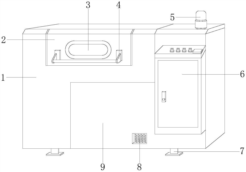
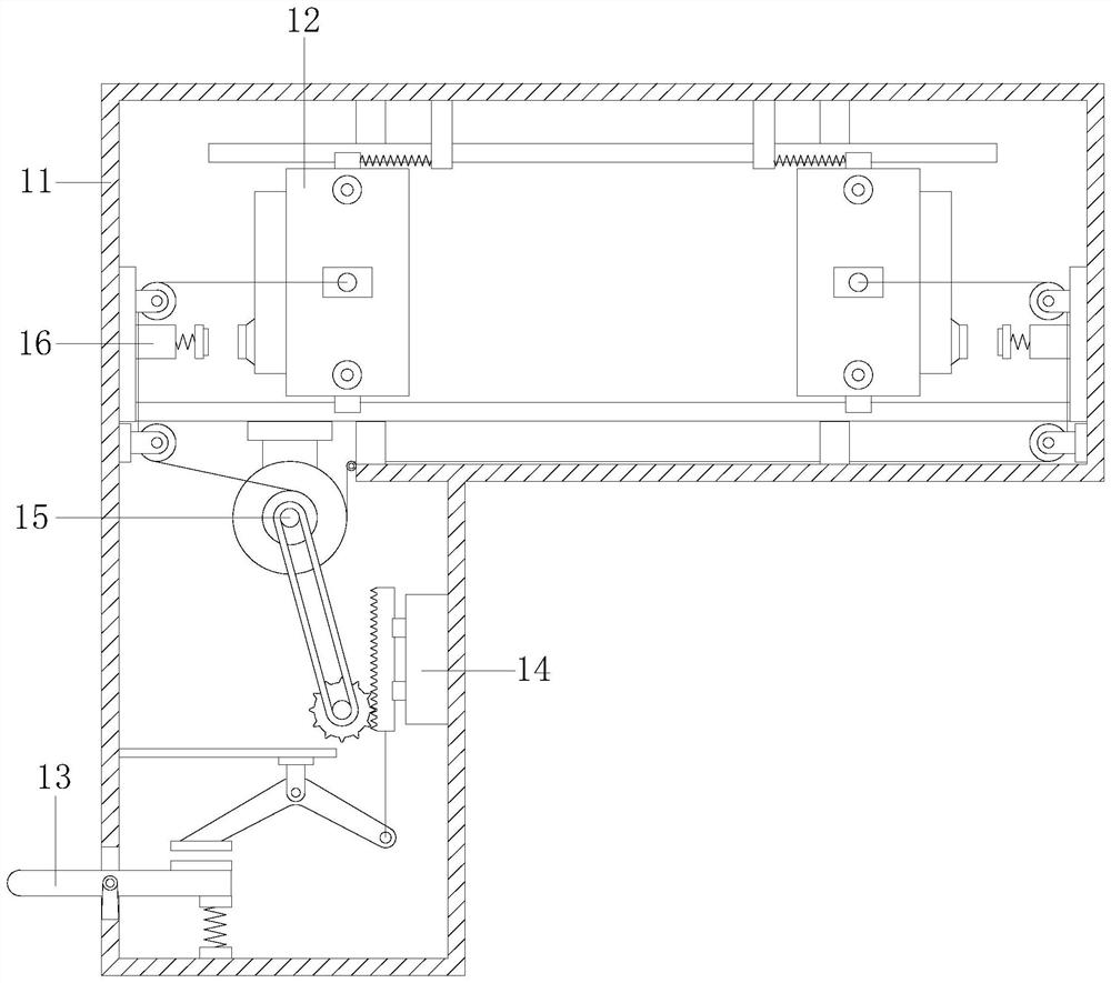
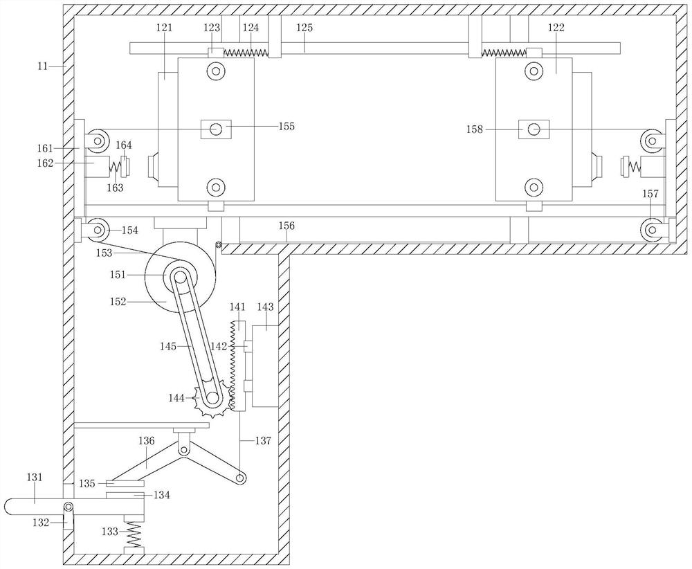
[0025] see Figure 1-Figure 4 , the present invention provides a continuous stranding and drawing forming device for cable conductors, the structure of which includes a stranding host 1, a box door 2, a viewing window 3, a handle 4, a warning light 5, an operating table 6, supporting feet 7, cooling holes 8, and a device base 9. A box door 2 is fixedly installed on the top of the twisted host 1, a window 3 is embedded in the front surface of the box door 2, a handle 4 is fixedly installed on the box door 2, and the window 3 is located directly above the handle 4, The warning light 5 is fixedly mounted on the top of the device base 9, the warning light 5 is electrically connected with the stranding host 1 through wires, the operating table 6 is fixedly installed on the device base 9, and the operating table 6 is connected with the twisting wire through the wires. The main unit 1 is electrically connected, the supporting feet 7 are fixedly welded to the bottom of the device base...


PUM


Abstract

The invention discloses a continuous twisting and drawing forming device for cable conductors, the structure of which comprises a twisting host, a box door, a window, a handle, a warning light, an operating table, supporting feet, heat dissipation holes, and a device base. The top of the twisting host is fixedly installed with The box door has a window embedded in the front surface of the box door, and a handle is fixedly installed on the box door. The window is located directly above the handle, and the warning light is fixedly installed on the top of the device base. Both ends of the head and tail are clamped to increase the clamping force. At the same time, the foot-operated mechanism drives the first fixed twisting mechanism and the tail fixed twisting mechanism to pull the bare conductor. After pulling, the first fixing mechanism is automatically opened by the touch mechanism. The twisting mechanism and the tail fixed twisting mechanism perform reverse twisting work, which speeds up the twisting speed. At the same time, the staff can carry out the cable twisting work without turning on the switch on the twisting mechanism, and the operation is more convenient.

Description

technical field [0001] The invention relates to the field of continuous twisting and drawing forming devices for cable conductors, in particular to a continuous twisting and drawing forming device for cable conductors. Background technique [0002] In cable production, twisting and drawing is an important part of cable production and a basic process widely used in cable production technology. However, the current cable conductor continuous twisting and drawing device has the following disadvantages: [0003] 1. In the working process of cable conductor stranding, multiple bare conductors are twisted together, because the principle of stranding will shorten the overall length and generate a certain amount of traction. The current devices are clamped at one end. The other end is twisted and twisted, so that not only the clamping force of the cable conductor is not enough, but also the twisting speed is not fast, which may cause the cable conductor to fall off during the twisti...

Claims


Application Information

Patent Timeline
Patent Type & Authority Patents(China)
IPC IPC(8): H01B13/00H01B13/02B21C1/00
CPCB21C1/00H01B13/00H01B13/0207
Inventor 官志超
Owner 安徽新信电气有限公司
Why Eureka
Try Eureka