
A shock wave pressure range measuring device

A pressure range and measuring device technology, applied in the direction of measuring blasting force, etc., can solve the problems of easily damaged test cables, difficult layout, data loss, etc., and achieve the effect of easy installation and low cost

Active Publication Date: 2020-08-21
XIAN MODERN CHEM RES INST
View PDF13 Cites 0 Cited by
  • Summary
  • Abstract
  • Description
  • Claims
  • Application Information

AI Technical Summary

Problems solved by technology

At present, the electrical measurement system consisting of pressure sensors and data acquisition instruments is commonly used in explosion shock wave pressure testing. The advantage of the electrical measurement system is that it can obtain a complete pressure waveform, but it has the following disadvantages: (1) The test sensor is susceptible to electromagnetic interference, and the test cable It is easily damaged in an explosive environment, resulting in data loss; (2) the electrical measurement system is limited by cost and workload, and it is difficult to deploy in large quantities; (3) the electrical measurement system needs to set the trigger conditions, and it is easy if the test system fails to trigger cause data loss

Method used


Image

  • A shock wave pressure range measuring device
  • A shock wave pressure range measuring device
  • A shock wave pressure range measuring device

Examples


Embodiment 1

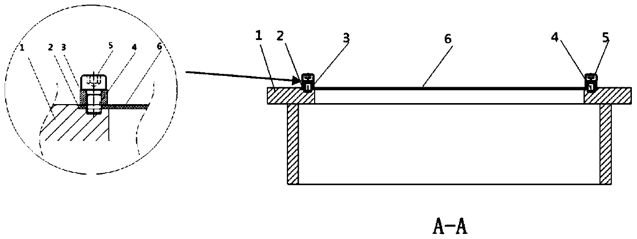
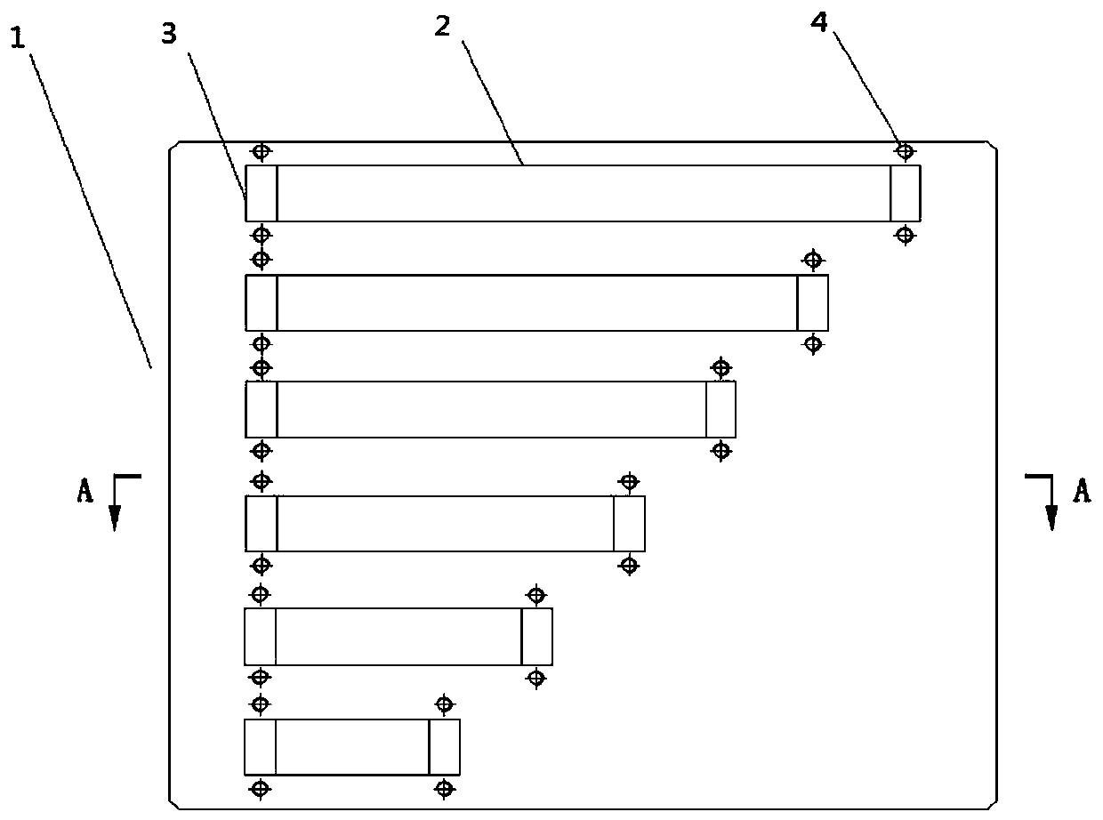
[0017] Comply with above-mentioned technical scheme, preferred embodiment of the present invention is as figure 1 As shown, the size of the installation base 1 is 270mm×270mm×72mm, the thickness of the upper surface is 12mm, and the thickness of the side wall is 8mm; the size of the diaphragm installation groove 2 is 20mm×10mm×0.8mm; the size of the bead 3 is 40mm×10mm ×5mm; bolt mounting hole 4 diameter is Φ5.5mm, compression bolt 5 is M5 screw; acrylic rectangular diaphragm 6 dimensions are 220mm×20mm×1mm; 190mm×20mm×1mm; 160mm×20mm×1mm; 130mm×20mm ×1mm; 100mm×20mm×1mm; 70mm×20mm×1mm.

[0018] Select 2kg spherical TNT explosives for static explosion test, hang the charge on the 1.2m high bomb rack, install the above measuring device at the positions where the projected distance from the charge ground is 2.5m, 3m, 4m, 5m, 6m, and measure the explosion The pressure range of the shock wave at the installation location, and a pressure sensor installed at the same distance for c...

Embodiment 2

[0025] In order to obtain the shock wave pressure range near a certain target in a certain dynamic explosion test, the shock wave pressure range measuring device of the present invention is used, and its overall composition and specific structure are the same as those in Embodiment 1. The ammunition used in the test was filled with TNT explosives, and the charge was 90kg.

[0026] Install the acrylic rectangular diaphragm 6 correspondingly in the diaphragm installation groove 2 of the shock wave range measuring device, then attach the bead 3 to the acrylic rectangular diaphragm 6, and then connect the pressing bolt 5 to the bolt installation hole 4 through the bead 3 installation hole , and compress the acrylic rectangular diaphragm 6 to form the shock wave pressure range measuring device used in this test. The test device of the present invention is arranged at the places where the horizontal distance from the target in the direction of 0°, 90°, 180° and 270° is 8m and 10m re...


PUM

PropertyMeasurementUnit
thicknessaaaaaaaaaa

Abstract

The invention discloses a shock wave pressure range measuring device for measuring a certain pressure range of shock waves in an explosion field, and belongs to shock wave pressure testing. The shockwave pressure range measuring device mainly comprises an installation base (1), a membrane installing groove (2), a pressing strip (3), a bolt installing hole (4), a pressing bolt (5) and an acrylic matrix membrane (6). The shock wave pressure action range is reflected on the basis of the fracture state of the acrylic matrix membrane which bears the action of shock waves. The shock wave pressure range measuring device is simple in structure and fixed to the explosion field when not used without influencing the testing of other explosion parameters; the measuring device is low in cost and convenient to operate, and a large number of measuring devices can be distributed for use.

Description

technical field [0001] The invention relates to a shock wave pressure range measuring device, which belongs to the field of shock wave pressure testing and is mainly used for measuring a certain pressure range of explosion shock waves. Background technique [0002] At present, for some high-value ammunition explosion tests or dynamic explosion damage tests, it is often concerned whether the explosion shock wave pressure at a certain distance or in a certain area in the explosion field reaches the expected value or range value, and these values ​​represent the critical damage to certain targets. The damage range can be evaluated according to its damage effect on the target. At present, the electrical measurement system consisting of pressure sensors and data acquisition instruments is commonly used in explosion shock wave pressure testing. The advantage of the electrical measurement system is that it can obtain a complete pressure waveform, but it has the following disadvanta...

Claims


Application Information

Patent Timeline
Patent Type & Authority Patents(China)
IPC IPC(8): G01L5/14
CPCG01L5/14
Inventor 姬建荣严家佳张俊锋孔霖王丹胡东常陈君
Owner XIAN MODERN CHEM RES INST
Learn More