Intelligent lock control method
A control method and smart lock technology, which is applied to building locks, non-mechanical transmission-operated locks, door/window accessories, etc., to achieve the effect of smart lock safety and improved functionality
- Summary
- Abstract
- Description
- Claims
- Application Information
AI Technical Summary
Problems solved by technology
Method used
Image
Examples
Embodiment 1
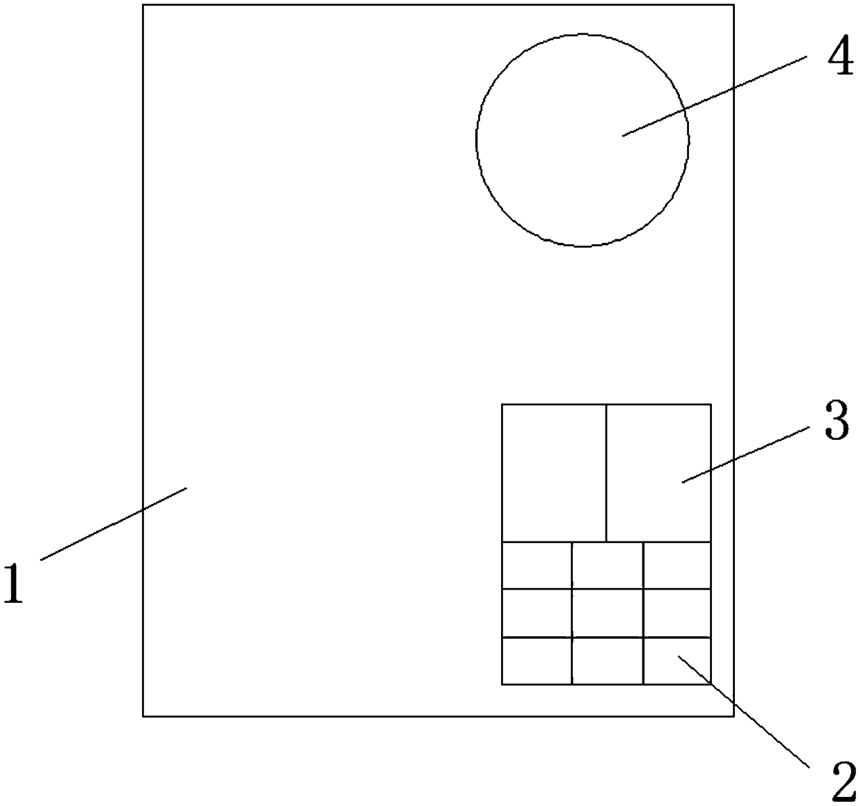
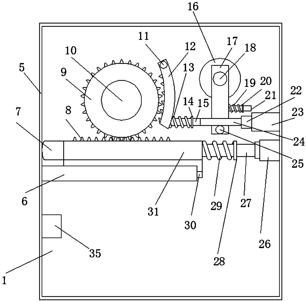
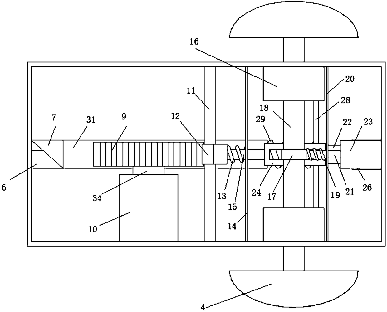
[0041] This embodiment provides a smart lock control method, such as Figure 1 to Figure 6 shown.
[0042] A kind of intelligent lock control method, comprises the following steps:
[0043] S1, identify the person who opens the door through the password keyboard 2 or the fingerprint identification device 3;
[0044] S2. After the identification of the door opener is successful, power on the motor 10, and the motor 10 drives the lock bar 31 to move toward the spring 3 29, and puts the dead bolt 7 into the lock body 1 to realize the automatic opening of the smart lock;
[0045] S3. When the smart lock is opened, the pawl 12 blocks the gear 9 to prevent the gear 9 from reversing, so that the lock tongue 7 remains in the lock body 1;
[0046] S4. When the door opener completes the door opening operation and closes the door, he turns the handle 4 and pops the dead bolt 7 out of the lock body 1 to realize the door locking operation.
[0047] In the step S2, after the motor 10 is ...
Embodiment 2
[0065] This embodiment provides a method for controlling an intelligent lock.
[0066] A kind of intelligent lock control method, comprises the following steps:
[0067] S1, identify the person who opens the door through the password keyboard 2 or the fingerprint identification device 3;
[0068] S2. After the identification of the door opener is successful, power on the motor 10, and the motor 10 drives the lock bar 31 to move toward the spring 3 29, and puts the dead bolt 7 into the lock body 1 to realize the automatic opening of the smart lock;
[0069] S3. When the smart lock is opened, the pawl 12 blocks the gear 9 to prevent the gear 9 from reversing, so that the lock tongue 7 remains in the lock body 1;
[0070] S4. When the door opener completes the door opening operation and closes the door, he turns the handle 4 and pops the dead bolt 7 out of the lock body 1 to realize the door locking operation.
Embodiment 3
[0072] This embodiment provides a method for controlling an intelligent lock.
[0073] A kind of intelligent lock control method, comprises the following steps:
[0074] S1, identify the person who opens the door through the password keyboard 2 or the fingerprint identification device 3;
[0075] S2. After the identification of the door opener is successful, power on the motor 10, and the motor 10 drives the lock bar 31 to move toward the spring 3 29, and puts the dead bolt 7 into the lock body 1 to realize the automatic opening of the smart lock;
[0076] S3. When the smart lock is opened, the pawl 12 blocks the gear 9 to prevent the gear 9 from reversing, so that the lock tongue 7 remains in the lock body 1;
[0077] S4. When the door opener completes the door opening operation and closes the door, he turns the handle 4 and pops the dead bolt 7 out of the lock body 1 to realize the door locking operation.
[0078] In the step S2, after the motor 10 is energized, the drive ...
PUM
 Abstract
Description
Claims
Application Information
 - R&D
- Intellectual Property
- Life Sciences
- Materials
- Tech Scout
- Unparalleled Data Quality
- Higher Quality Content
- 60% Fewer Hallucinations
Browse by: Latest US Patents, China's latest patents, Technical Efficacy Thesaurus, Application Domain, Technology Topic, Popular Technical Reports.
© 2025 PatSnap. All rights reserved.Legal|Privacy policy|Modern Slavery Act Transparency Statement|Sitemap|About US| Contact US: help@patsnap.com


