
Rod conveying line control method and device

A control method and technology of a control device, which can be applied to conveyor control devices, conveyors, conveyor objects, etc., can solve problems such as system failure, complexity, and complex overall control methods.

Inactive Publication Date: 2019-03-12
DENGFENG QIMINGXUAN PROGRAM CONTROL EQUIP
View PDF6 Cites 0 Cited by
  • Summary
  • Abstract
  • Description
  • Claims
  • Application Information

AI Technical Summary

Problems solved by technology

[0004] The purpose of the present invention is to provide a method and device for controlling the rod conveying line, which is used to solve the problem that the existing rod conveying on the conveying line is relatively complex through the overall control method, and it is easy to cause system failure and stop the conveying line due to unexpected situations. The problem of lower production efficiency
[0005] In order to realize the transmission of rods through the conveyor line, the existing rods are conveyed on the conveyor line through the overall control method is relatively complicated, and it is prone to unexpected situations that lead to system failures that cause the conveyor line to stop and cause low production efficiency.

Method used


Image

  • Rod conveying line control method and device
  • Rod conveying line control method and device

Examples


Embodiment 1

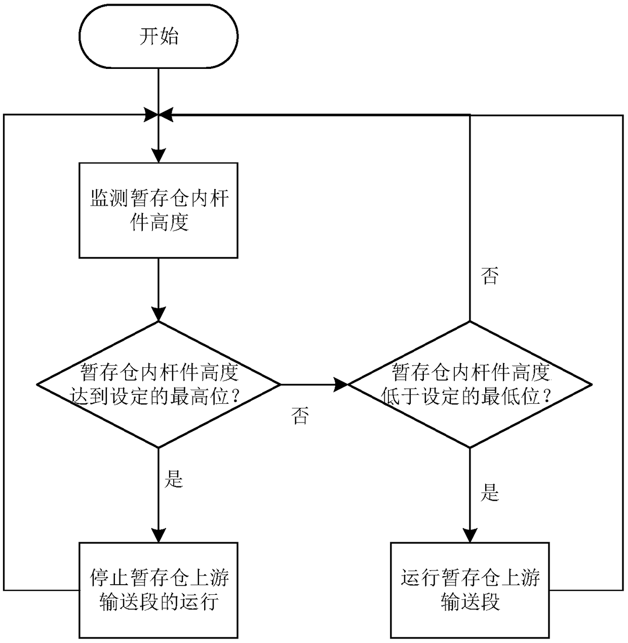
[0020] The invention provides a method for controlling a rod conveying line, such as figure 1 shown, including the following steps:

[0021] 1) Monitor the height of the rods in the temporary storage warehouse;

[0022] 2) If the height of the rods in the temporary storage warehouse reaches the set highest position, the operation of the upstream conveying section of the temporary storage warehouse will be stopped.

[0023] If the height of the rods in the temporary storage warehouse does not reach the set maximum position, the upstream conveying section of the temporary storage warehouse will run.

[0024] The height of the rods in the temporary storage can be detected by sensors such as height sensors and position sensors. By detecting the height of the rods in the temporary storage, the control of the upstream conveying section of the temporary storage can be realized, which makes the control of the conveying line simpler and more convenient. This kind of linkage control c...

Embodiment 2

[0026] The invention provides a method for controlling a rod conveying line, such as figure 2 As shown, on the basis of Embodiment 1 of the above method, when the height of the poles in the temporary storage warehouse does not reach the set highest level, it is also judged whether the height of the poles in the temporary storage warehouse is lower than a set minimum level, if , then run the upstream conveying section of the temporary storage warehouse.

[0027] Several rods in the temporary storage warehouse have just been taken away, and the upstream conveying section will send a corresponding number of rods into the temporary storage warehouse at the next moment. At this time, the upstream conveying section must be controlled to stop running. Stopping the upstream conveying section will easily reduce the life of the driving mechanism. Therefore, in order to avoid the above situation, through a set minimum position judgment, it is possible to avoid frequent start and stop of...


PUM


Abstract

The invention relates to the field of automatic control, in particular to a rod conveying line control method and device. The device comprises a height sensor, a processor and a storage which are arranged in a temporary storage bin; the processor is in sampling connection with the height sensor; the processor is in control connection with a driving mechanism used for driving a conveying section onthe upstream side of the temporary storage bin; the processor is used for executing a program instruction stored in the storage to achieve the purpose of monitoring the height of rods in the temporary storage bin; and if the height of the rods in the temporary storage bin reaches the set highest value, running of the conveying section on the upstream side of the temporary storage bin is stopped.According to the rod conveying line control method and device, control over the conveying section on the upstream side of the temporary storage bin is achieved by detecting the height of the rods in the temporary storage bin, therefore, control over the conveying line is easier, and running of the conveying line composed of two or more than two conveying sections can be achieved through the control mode; and one conveying line can be provided with multiple control devices, each control device only controls the upstream conveying section related to the control device, therefore, orderly conveying is achieved, faults are not prone to being generated, and the reliability is high.

Description

technical field [0001] The invention relates to the field of automation control, in particular to a control method and device for a rod conveying line. Background technique [0002] The production line, assembly line, etc. realize the production of products through automatic control. In the automatic production process, there are some items that need to be recycled to the entrance of the production line, such as surplus materials, fixing parts, etc. These items need to be recycled. How to transport the above-mentioned items that need to be recycled to At the entrance of the production line, there are some existing methods. For example, for areas with a large production space, items can be recycled by setting up a recycling vehicle; for example, if it is inconvenient to directly recycle, the recycled items can be collected manually and sent to the entrance of the production line . [0003] The noodle production line needs to hang the noodles through the noodle rod, and then ...

Claims


Application Information

Patent Timeline
Patent Type & Authority Applications(China)
IPC IPC(8): B65G43/10A21C9/08A21C9/00
CPCA21C9/00A21C9/08B65G43/10B65G2201/0202B65G2203/042
Inventor 付俊辉李文凯焦翠萍宗向东
Owner DENGFENG QIMINGXUAN PROGRAM CONTROL EQUIP
Learn More