
Rotating arm joint variable in stiffness and series of positioning device having same

A technology of variable stiffness and rotating arm, which is applied in the direction of bogie, axle box installation, transportation and packaging, etc., can solve the problem that the stiffness value cannot be changed, and achieve the effect of improving dynamic performance

Pending Publication Date: 2019-03-12
CRRC CHANGCHUN RAILWAY VEHICLES CO LTD
View PDF0 Cites 25 Cited by
  • Summary
  • Abstract
  • Description
  • Claims
  • Application Information

AI Technical Summary

Problems solved by technology

[0002] The primary positioning of the existing rail vehicle bogie adopts a rotary arm positioning structure, and the joints of the rotary arm are all of constant stiffness, that is, the stiffness value cannot be changed

Method used


Image

  • Rotating arm joint variable in stiffness and series of positioning device having same
  • Rotating arm joint variable in stiffness and series of positioning device having same
  • Rotating arm joint variable in stiffness and series of positioning device having same

Examples


Embodiment Construction

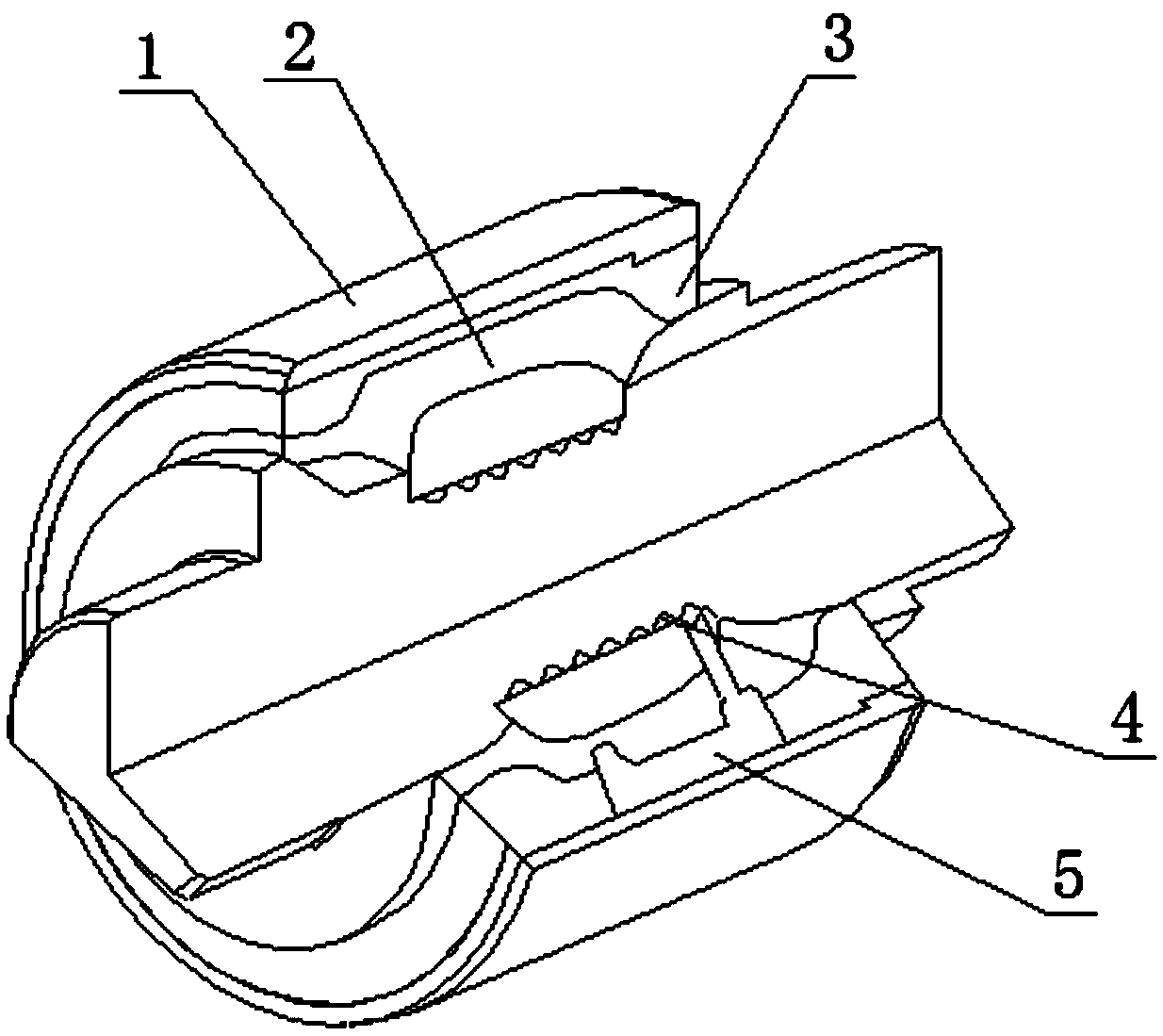
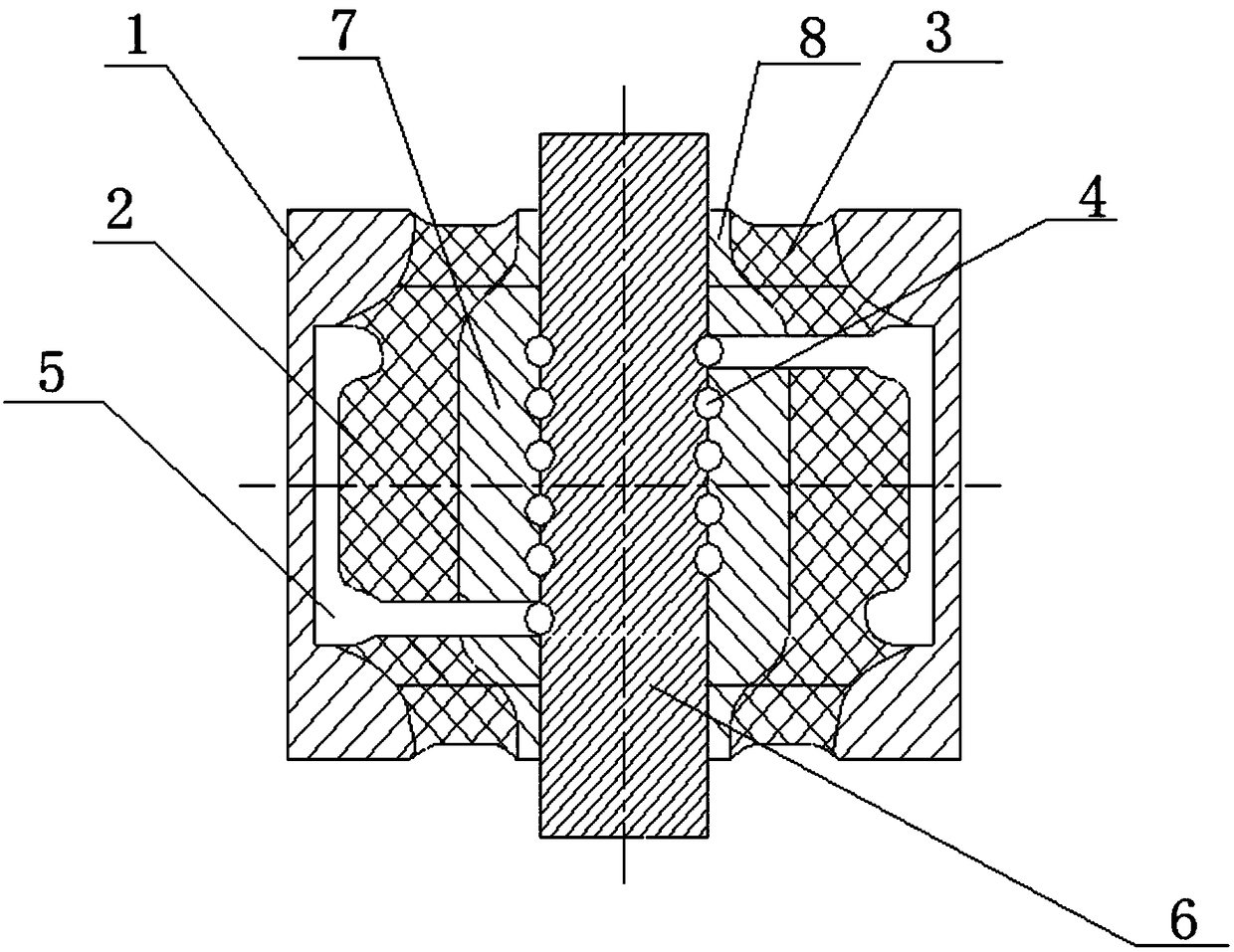
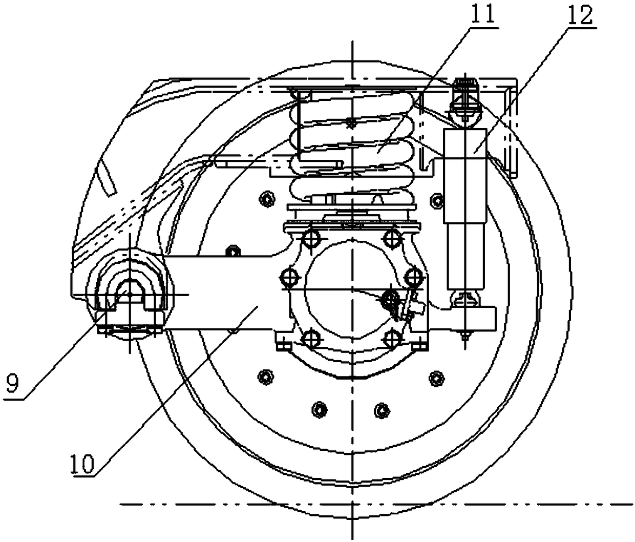
[0012] refer to Figure 1-Figure 2 , the specific embodiment of the present invention comprises jacket 1, main spring, auxiliary spring, mandrel 6, and main spring is vulcanized into one by two parts of rubber 2 and metal part 7, and the inner circumference of main spring metal part has semicircular spiral groove, and the main spring Auxiliary springs are pressed at both ends, and the auxiliary spring is also corresponding to the main spring, which is vulcanized by two parts of rubber 3 and metal part 8. The outer circumference of the mandrel corresponds to the semicircular spiral groove on the inner circumference of the main spring metal part The semicircular spiral groove, the metal parts of the main spring and the mandrel are pressed together, and the two semicircular spiral grooves are connected to form a spiral cavity. The mandrel is a symmetrical axis, and two oil chambers 5 are arranged between the outer jacket and the main spring, and the two oil chambers communicate w...


PUM


Abstract

The invention relates to a rotating arm joint variable in stiffness. The rotating arm joint comprises an outer sleeve, a main spring, auxiliary springs and a mandrel, an oil pipeline is wound around the surface of the mandrel, the main spring is formed by vulcanizing rubber and a metal piece into a whole part, the metal piece part of the main spring is in press fit with the mandrel, the auxiliarysprings are in press fit with the two ends of the main spring, and each auxiliary spring is also formed by vulcanizing the rubber and the metal piece into a whole part corresponding to the main spring; the outer sleeve is in press fit with the peripheries of the main spring and auxiliary springs, the outer sleeve and the main spring define an oil chamber, and upper and lower openings of the oil chamber are communicated with two ports of the oil pipeline respectively. The oil pipeline is arranged between the mandrel and the main spring, and the oil chamber is formed between the main spring andthe outer sleeve. During running of a car, the oil chamber is compressed when the springs are deformed by a force, oil flows in the pipeline to generate a damping force, and the purpose of changing stiffness is achieved. A series of positioning devices having the rotating arm joint can meet different requirements of a linear line and a curved line, and the dynamic performance of the car is improved.

Description

technical field [0001] The invention relates to a rotary arm node of a primary positioning device for a rail vehicle, in particular to a variable stiffness rotary arm node and a primary positioning device. Background technique [0002] The primary positioning of the existing rail vehicle bogie adopts a rotary arm positioning structure, and the joints of the rotary arm are all of constant stiffness, that is, the stiffness value cannot be changed. However, when the actual vehicle is running, high stability requires high longitudinal stiffness, and good curve passing performance requires low longitudinal stiffness. In order to solve this conflict, a new type of pivoting arm node was developed to realize the variable stiffness value of the pivoting arm node. To adapt to the different requirements of straight lines and curved lines, improve vehicle dynamics performance. Contents of the invention [0003] The object of the present invention is to provide a pivoting arm node wit...

Claims


Application Information

Patent Timeline
IPC IPC(8): B61F5/30
CPCB61F5/308
Inventor 张莉姜朝勇董磊程建会魏苇
Owner CRRC CHANGCHUN RAILWAY VEHICLES CO LTD
Learn More