Eureka AIR delivers breakthrough ideas for toughest innovation challenges, trusted by R&D personnel around the world.

Semi-automatic sample feeding needle

A semi-automatic, sample-feeding technology, applied in the field of sample-feeding needles, which can solve the problems of affecting accuracy, poor control of the push rod pulling speed, time-consuming and labor-intensive, etc., to achieve the effect of avoiding thermal expansion and contraction.

Active Publication Date: 2019-03-12
江苏阀邦半导体材料科技有限公司
View PDF9 Cites 2 Cited by
  • Summary
  • Abstract
  • Description
  • Claims
  • Application Information

AI Technical Summary

Problems solved by technology

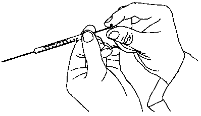
The sample delivery needle with this structure has the following disadvantages: 1. The pulling speed of the push rod 3' is not easy to control, and manual control has certain limitations; 2. When the hand supports the needle tube 1', the finger surface will touch the needle tube 1', causing changes in the temperature of the liquid medicine in the tube, which may affect the accuracy of subsequent experiments
[0003] When adding medicine to the exact position of the animal experiment, in order to keep the same process for each experiment, two researchers must be used, one researcher fixes the animal test body, the other researcher inserts the needle to the exact position (such as the hippocampus of the brain), and fixes the needle with one hand , the other hand implements fixed-rate drug delivery, which is time-consuming and labor-intensive
The drug delivery rate depends on the hand feel, and it is difficult to be consistent every time, which will affect the results of quantitative analysis to a certain extent

Method used


Image

  • Semi-automatic sample feeding needle
  • Semi-automatic sample feeding needle
  • Semi-automatic sample feeding needle

Examples


Embodiment Construction

[0017] The following will clearly and completely describe the technical solutions in the embodiments of the present invention with reference to the accompanying drawings in the embodiments of the present invention. Obviously, the described embodiments are only some, not all, embodiments of the present invention. Based on the embodiments of the present invention, all other embodiments obtained by persons of ordinary skill in the art without making creative efforts belong to the protection scope of the present invention.

[0018] see image 3 , the semi-automatic sample delivery needle of the present invention, it comprises needle tube 1 and needle head 2, and it also comprises cylinder type body 3, and needle tube 1 end is connected with needle head 2, and rotating needle head 2 is relatively easy to replace, and the other end of needle tube 1 is connected with cylinder type body 3 connection, the other end of the needle tube 1 extends into the cylinder body 3, and the two are ...


PUM


Abstract

The invention discloses a semi-automatic sample feeding needle, which comprises a needle tube, a needle head and a cylinder-shaped body, wherein one end of the needle tube is connected with the needlehead, the other end of the needle tube is connected with the cylinder-shaped body, the outside of the cylinder-shaped body is connected with an upper quick pressing rod through a balance bracket, thequick pressing rod is arranged above the needle tube and the cylinder-shaped body and is parallel to the needle tube and the cylinder-shaped body, the front end of the quick pressing rod is providedwith a braking spring which acts downwards on the outer wall of the cylinder-shaped body, the rear end of the quick pressing rod is provided with a speed regulating guide rod, the lower end of the speed regulating guide rod acts on the inner side of the cylinder-shaped body, and the cylinder-shaped body is internally provided with a liquid quantity pull rod used for drawing liquid medicine. The needle is a semi-automatic sample feeding needle and can trigger a device to quickly feed samples after the needle is inserted, hands do not directly contact the tube wall, and the reagent can be prevented from expanding with heat and contracting with cold. The semi-automatic sample feeding needle can be used, by one researcher, to independently complete the fixed-point, positioning, fixed-speed andquantitative medicine feeding operation for an animal experiment body.

Description

technical field [0001] The invention relates to a sample delivery needle, in particular to a semi-automatic sample delivery needle. Background technique [0002] An existing liquid medicine sample delivery needle, figure 1 and 2 As shown, it has a needle tube 1', a needle head 2' and a push rod 3', and the needle tube 1' is a transparent material with scales. When operating the experiment, the user holds the liquid medicine bottle with one hand and the sample delivery needle with the other hand, inserts the needle 2' of the sample delivery needle into the liquid medicine bottle, supports the needle tube 1' with one hand, and holds the needle tube 1' with the other hand. Pull the push rod 3', by experience, control the pulling speed of the push rod 3'. The sample delivery needle with this structure has the following disadvantages: 1. The pulling speed of the push rod 3' is not easy to control, and manual control has certain limitations; 2. When the hand supports the needle...

Claims


Application Information

Patent Timeline
IPC IPC(8): A61D7/00A61M5/20
CPCA61D7/00A61M5/2033A61M2005/2026A61M2250/00
Inventor 冯佳
Owner 江苏阀邦半导体材料科技有限公司
Why Eureka
Eureka Blog
Learn More