
An automatic cooling sealed power cabinet

An automatic cooling and power cabinet technology, applied in the cooling/ventilation of substation/switchgear, electrical components, details of substation/switch layout, etc., can solve problems such as damage to electrical equipment, and achieve the effect of avoiding air humidity

Active Publication Date: 2020-04-10
江苏楚能电控设备有限公司
View PDF5 Cites 0 Cited by
  • Summary
  • Abstract
  • Description
  • Claims
  • Application Information

AI Technical Summary

Problems solved by technology

[0003] In the process of installing heat dissipation equipment on the power cabinet, although the purpose of heat dissipation can be achieved, in the case of rainy days, due to the ventilation setting, the humid air will be further transported into the power cabinet, and the humidity of the air will be further attached to the power cabinet. On the electrical equipment, which will further damage the electrical equipment due to the humidity of the air

Method used


Image

  • An automatic cooling sealed power cabinet
  • An automatic cooling sealed power cabinet
  • An automatic cooling sealed power cabinet

Examples


Embodiment Construction

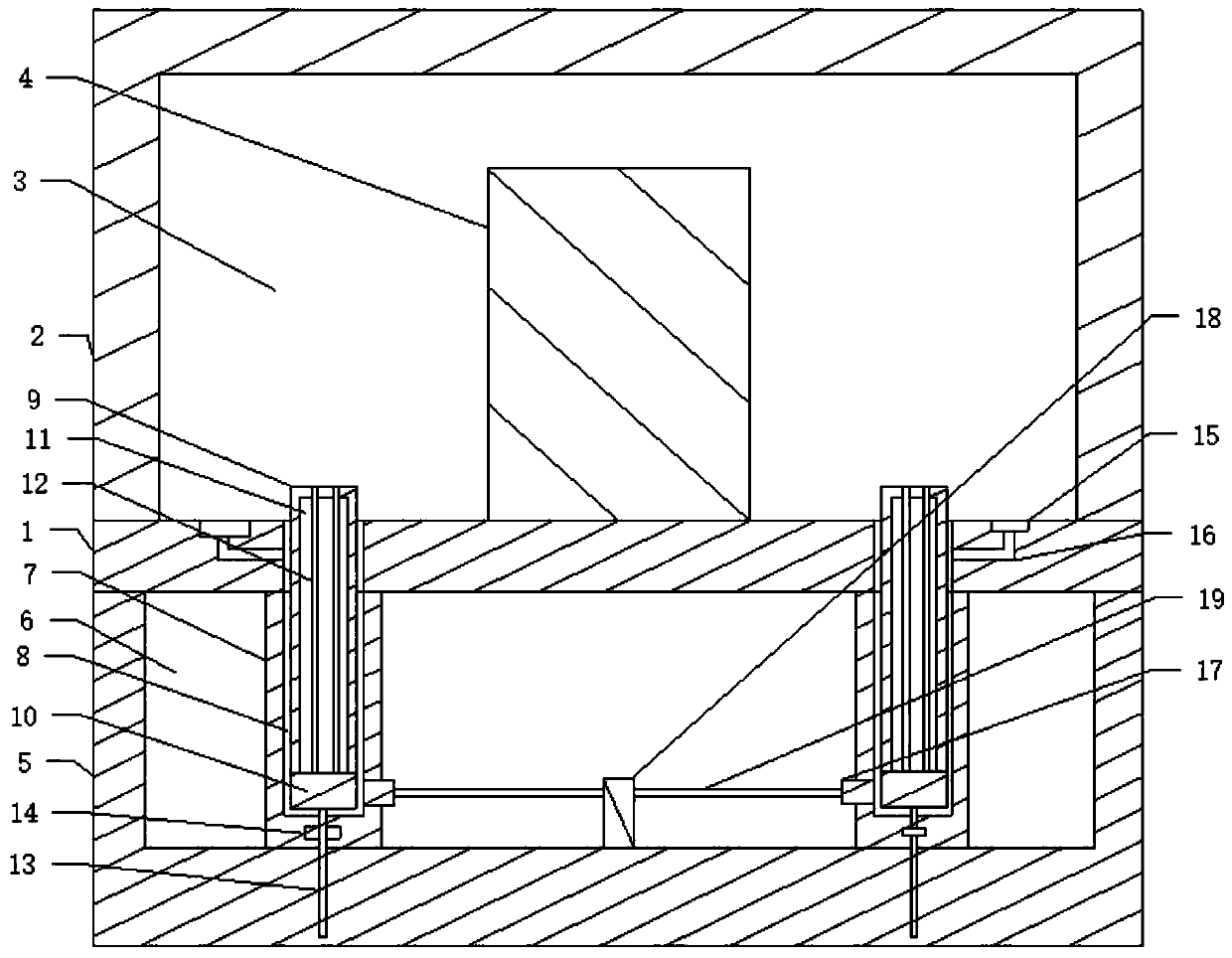
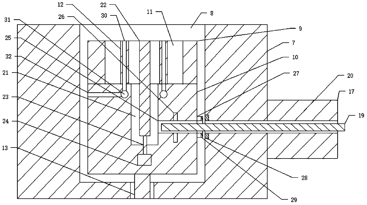
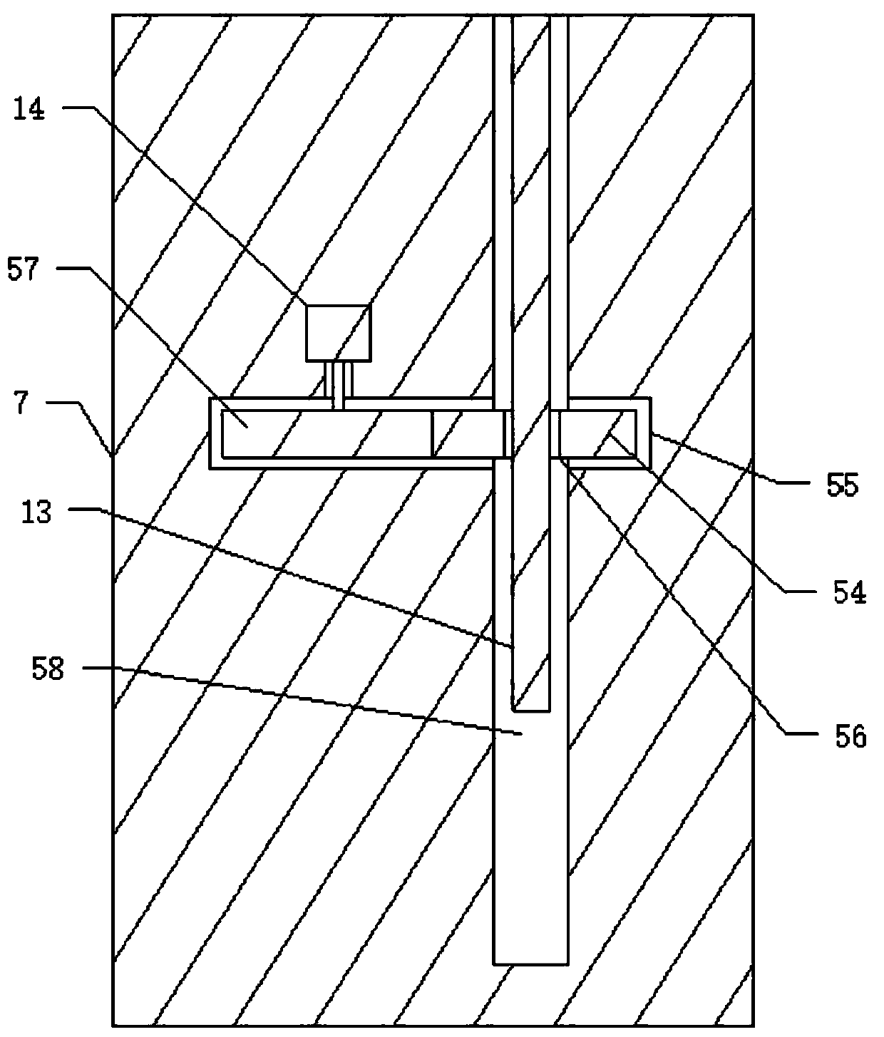
[0036] Such as Figure 1 to Figure 8 As shown, an automatic cooling sealed power cabinet includes a sealed cabinet body 2, a cabinet inner cavity 3 is arranged in the sealed cabinet body 2, a control cabinet 4 is arranged in the cabinet inner cavity 3, the The top of the sealed cabinet body 2 is provided with a fixed base 1, and the bottom of the fixed base 1 is provided with a cooling bottom box 5, and the cooling bottom box 5 is buried in the ground, and a cooling tank groove is arranged in the cooling bottom box 5 6. Fine sand is provided in the cooling tank tank 6, and a plurality of conveying cylinders 7 are provided in the cooling tank tank 6, and a conveying cylinder 7 is respectively provided with a corresponding communication with the inner cavity 3 of the cabinet. The first sliding chamber 8, a sliding cooling cylinder 9 is respectively arranged in the first sliding chamber 8, and a cooling cavity 11 is respectively arranged in the cooling cylinder 9, and a plurality...


PUM


Abstract

The invention discloses an automatic cooling and sealing power cabinet, which comprises a sealed cabinet body, a fixed base is arranged on the top of the sealed cabinet, and a cooling bottom box is arranged on the bottom of the fixed base, inside the cooling bottom box A cooling tank groove is provided, and fine sand is arranged in the cooling tank groove, and a plurality of conveying cylinders are arranged in the cooling tank groove, and a first sliding chamber is respectively arranged in the conveying cylinders, and the first sliding chambers A sliding cooling cylinder is respectively arranged in the cavity, and a cooling chamber is respectively arranged in the cooling cylinder, and a plurality of cooling pipes are arranged in the cooling chamber, and a Corresponding to the connected cooling air holes, the fine sand in the cooling tank can be further cooled by the underground temperature, so that the cooling pipe can be further lowered, so that the air in the cabinet cavity can be circulated to the cooling air. In the process of holes, the purpose of cooling the inner cavity of the cabinet is further achieved.

Description

technical field [0001] The invention relates to electric equipment, in particular to an automatic cooling and sealing power cabinet, in particular to an automatic cooling and sealing power cabinet capable of cooling the inside of the power cabinet through underground fine sand. Background technique [0002] With the strong demand for power, the demand for power equipment has further increased. Among the current power equipment, the power cabinet is one of the common equipment, so that the electrical equipment can be further centrally set through the power cabinet, so that It can further control the electricity consumption of residents. Since the power cabinet will generate a lot of heat during operation, ventilation equipment will be installed on the power cabinet, so that the ventilation equipment can be further used to further control the electricity in the power cabinet. The heat is dissipated to ensure the normal operation of the power cabinet. Although the purpose of ve...

Claims


Application Information

Patent Timeline
Patent Type & Authority Patents(China)
IPC IPC(8): H02B1/56H02B1/30
CPCH02B1/30H02B1/565
Inventor 不公告发明人
Owner 江苏楚能电控设备有限公司
Learn More