Decorative part with lamps

A technology of decorative parts and lights, which is applied to the parts of lighting devices, lampshades, lighting devices, etc., can solve the problems of unclear contours of illuminants, gap errors, and time-consuming production, and achieve better luminous display effects and smaller sizes. The effect of high precision and stable integrated structure

Pending Publication Date: 2019-03-08
NINGBO MINTH AUTOMOTIVE PARTS RES&DEV CO LTD
View PDF0 Cites 4 Cited by
  • Summary
  • Abstract
  • Description
  • Claims
  • Application Information

AI Technical Summary

Problems solved by technology

[0002] At present, there are two types of manufacturing processes for luminescent decorative parts on the market. One is to bond a single luminescent plastic part to the back of a single metal part formed into a pattern corresponding to the plastic part at room temperature. In this process, each metal part and plastic luminous part is bonded and combined at room temperature, the production is very time-consuming, the production efficiency is low, the structural stability is not high, and there is no zero gap at the edge of the metal part and the plastic luminous part, there is A certain gap error will reduce the appearance image of the product circle, and the outline of the illuminant is not clear enough, etc.
The second is to meet the one-piece production process through the deformation of individual graphics. Although the one-piece luminous decoration made by graphic deformation meets the requirements of zero gap, the artistic deformation of the font violates the original effect of the car logo font.

Method used


Image

  • Decorative part with lamps
  • Decorative part with lamps
  • Decorative part with lamps

Examples


Embodiment Construction

[0016] The technical solution of the present invention will be further described and illustrated through specific embodiments and accompanying drawings below. Unless otherwise specified, the raw materials used in the examples of the present invention are commonly used raw materials in the art, and the methods used in the examples are conventional methods in the art.

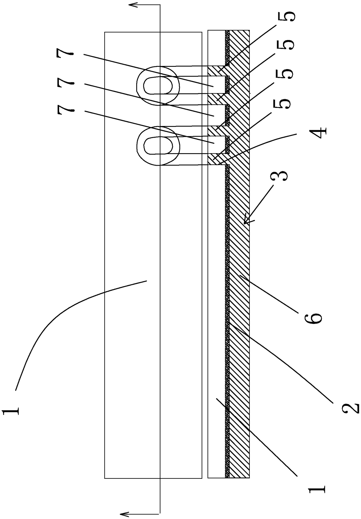
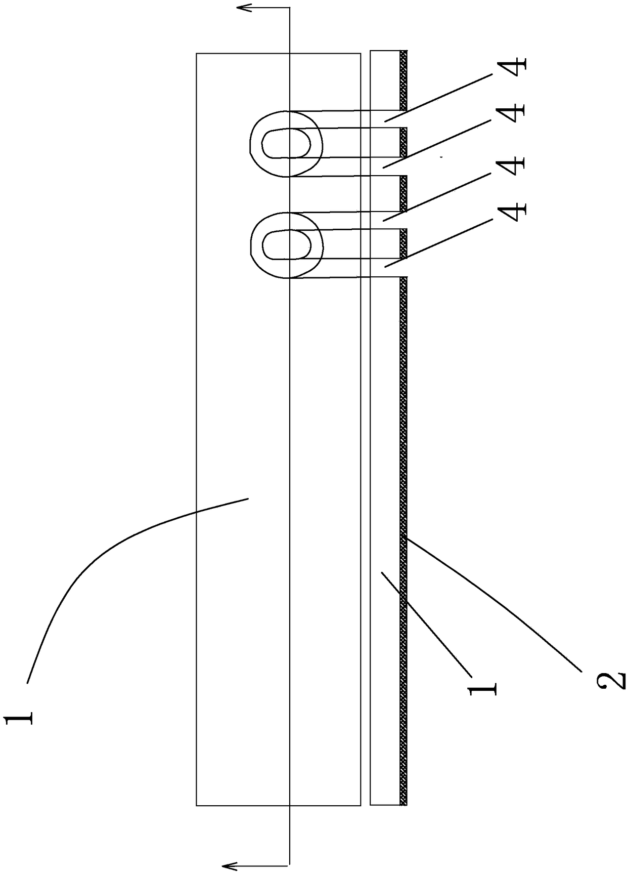
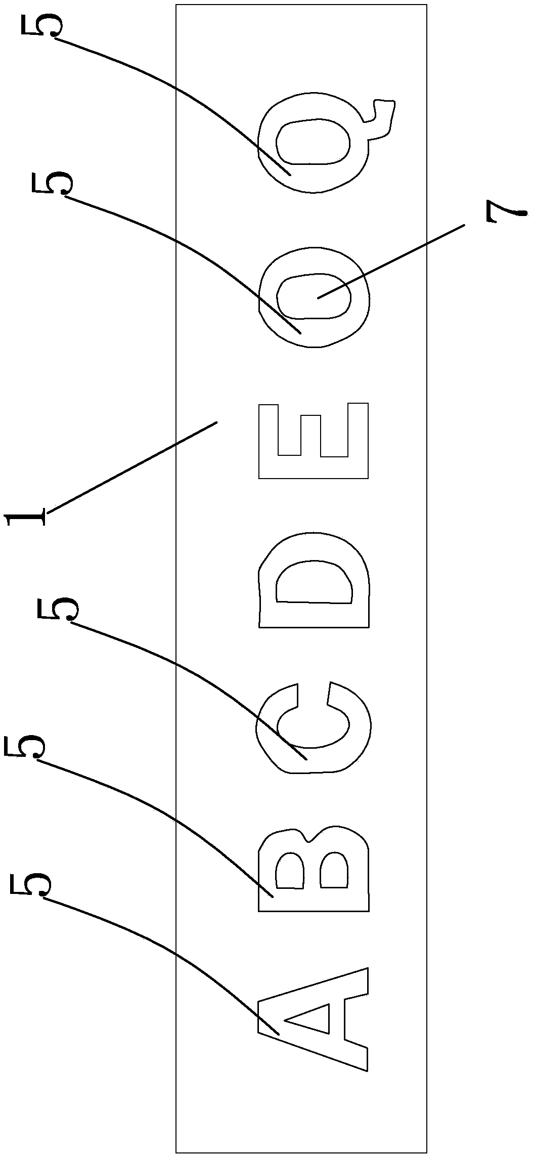
[0017] In the figure, sheet body 1; glue body 2; light-transmitting plastic body 3; through hole 4; font light-transmitting part 5; overall light-transmitting part 6;

[0018] Such as Figure 4 as well as image 3 As shown, the decorative part with lights can be formed with ABCDEOQ expected graphic fonts etc. on its upper surface. Here, this patent is explained with the expected graphic font of OQ. The light-transmitting plastic body 3, the light-transmitting rate of the light-transmitting plastic body 3 is ≥ 60%, and the haze is ≥ 80%, which is conducive to the light transmission of the entire decorative part,...


PUM

PropertyMeasurementUnit
transmittivityaaaaaaaaaa
hazeaaaaaaaaaa

Abstract

The invention belongs to the technical field of automobile accessories, and provides a decorative part with lamps. The decorative part with the lamps comprises a sheet body, a glue body and a light-transmitting plastic body. Through holes corresponding to an expected graphic font are formed in the sheet body. The integrated light-transmitting plastic body is formed by injection molding filling ofthe lower surface of the sheet body and the through holes after plastic melt is injected. The light-transmitting plastic body is divided into a whole light-transmitting part and a font character-shaped light-transmitting part, the whole light-transmitting part is adhered to the lower surface of the sheet body through the glue body to form a whole, and the through holes are formed by injection molding filling of the font character-shaped light-transmitting part and form the expected graphic font on the sheet body. The decorative part with the lamps has the beneficial effects that the metal sheet body and the light-transmitting plastic body are together formed in an injection molding mode, the through holes formed in the metal sheet body in an etched mode are filled with the light-transmitting plastic body during injection molding, seamless butt joint of the metal and the plastic is realized, the integrated structure is stable, the size precision is high, and the light-emitting display effect of the decorative part is better.

Description

technical field [0001] The invention relates to a decorative part, in particular to a decorative part with lights, and belongs to the technical field of auto parts. Background technique [0002] At present, there are two types of manufacturing processes for luminescent decorative parts on the market. One is to bond a single luminescent plastic part to the back of a single metal part formed into a pattern corresponding to the plastic part at room temperature. In this process, each metal part and plastic luminous part is bonded and combined at room temperature, the production is very time-consuming, the production efficiency is low, the structural stability is not high, and there is no zero gap at the edge of the metal part and the plastic luminous part, there is A certain gap error will reduce the appearance image of the product circle, and the outline of the illuminant is not clear enough. The second is to meet the one-piece production process through the deformation of ind...

Claims


Application Information

Patent Timeline
Patent Type & Authority Applications(China)
IPC IPC(8): F21S8/00F21V3/06B29C45/14F21Y115/10
CPCB29C45/14B29C45/14221F21S8/00F21V3/062F21Y2115/10
Inventor 胡益男杨荣昌何泽陆
Owner NINGBO MINTH AUTOMOTIVE PARTS RES&DEV CO LTD
Why Eureka
Try Eureka