
Multilayer circulating tunnel furnace

A technology of multi-layer circulation and tunnel furnace, which is applied in the direction of printing, printing machines, general parts of printing machinery, etc., can solve the problem of large space occupied by tunnel furnaces, prolong the drying time, save costs, and reduce the occupied space Effect

Pending Publication Date: 2019-03-08
SHENZHEN VILITY AUTOMATION EQUIP
View PDF0 Cites 4 Cited by
  • Summary
  • Abstract
  • Description
  • Claims
  • Application Information

AI Technical Summary

Problems solved by technology

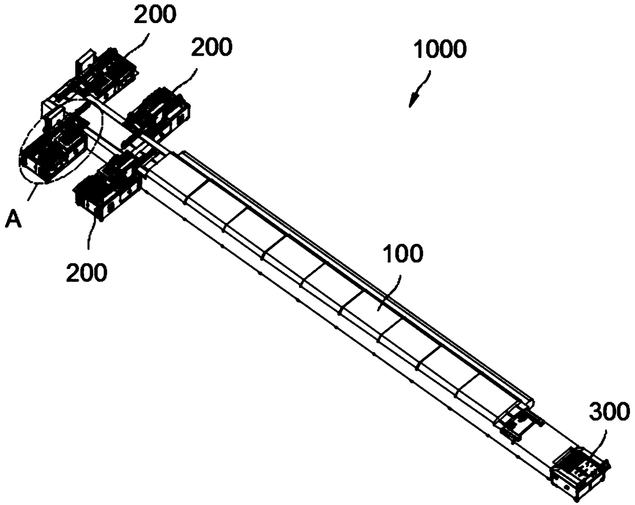
[0004] The main purpose of the present invention is to propose a multi-layer circulating tunnel furnace, aiming at solving the technical problem that the tunnel furnace occupies a large space in the related art

Method used


Image

  • Multilayer circulating tunnel furnace
  • Multilayer circulating tunnel furnace
  • Multilayer circulating tunnel furnace

Examples


Embodiment Construction

[0050] The following will clearly and completely describe the technical solutions in the embodiments of the present invention with reference to the accompanying drawings in the embodiments of the present invention. Obviously, the described embodiments are only part of the embodiments of the present invention, not all of them. Based on the embodiments of the present invention, all other embodiments obtained by persons of ordinary skill in the art without creative efforts fall within the protection scope of the present invention.

[0051] It should be noted that if there is a directional indication (such as up, down, left, right, front, back...) in the embodiment of the present invention, the directional indication is only used to explain the position in a certain posture (as shown in the accompanying drawing). If the specific posture changes, the directional indication will also change accordingly.

[0052]In addition, if there are descriptions involving "first", "second" and s...


PUM


Abstract

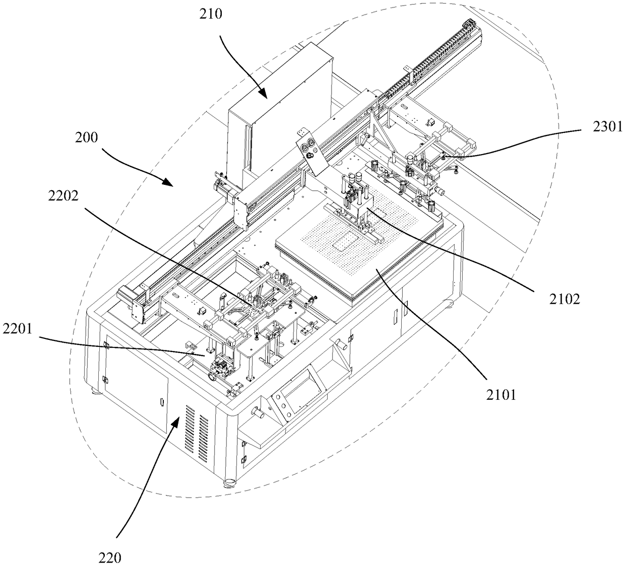
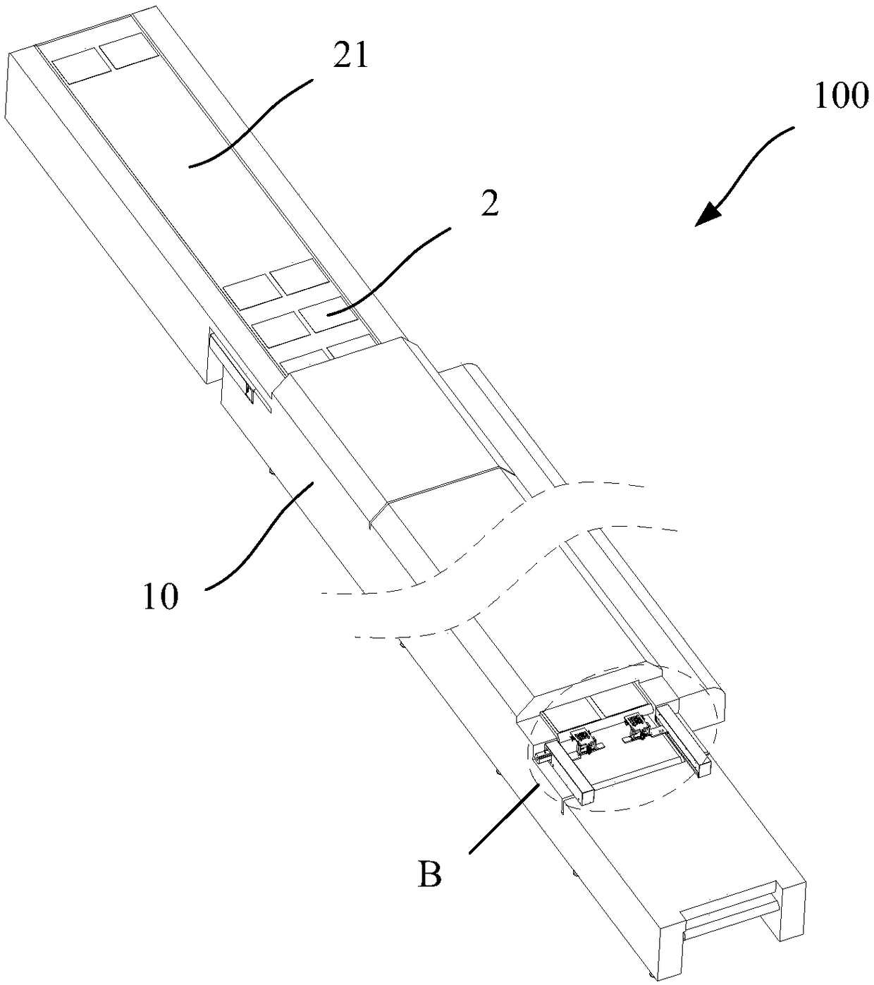
The invention discloses a multilayer circulating tunnel furnace. The multilayer circulating tunnel furnace comprises a housing, a plurality of layers of in-furnace conveyor belts and a transfer mechanical hand, wherein the housing is provided with a drying channel; the in-furnace conveyor belts are arranged in the drying channel vertically in a spaced mode, and are used for transferring a printingmaterial; and the transfer mechanical hand is mounted on the housing and is used for converting the printing material among different layers of the in-furnace conveyor belts, so that the printing material is transferred in a circulating mode on different layers of the in-furnace conveyor belts. According to the multilayer circulating tunnel furnace disclosed by the invention, the multiple layersof in-furnace conveyor belts are arranged, and the transfer mechanical hand is arranged, so that the printing material moves in a circulating mode among different layers of the in-furnace conveyor belts, drying time, in the multilayer circulating tunnel furnace, of the printing material is prolonged in case of not increasing the length of the multilayer circulating tunnel furnace, and occupied space of the multi-layer circulating tunnel furnace can be reduced, and therefore, the multilayer circulating tunnel furnace can be suitable for a relatively small production site, and the cost can be reduced.

Description

technical field [0001] The invention relates to the technical field of printing material drying, in particular to a multi-layer circulating tunnel furnace. Background technique [0002] In the field of printing technology, it is necessary to dry / dry the printed printing materials (such as sheets). In related technologies, a tunnel furnace is installed at the output end of the printing equipment. The printing materials printed by the equipment enter the drying channel of the tunnel furnace through the single-layer conveyor belt, and the circulating hot air dries the printing materials. [0003] However, the above-mentioned tunnel furnace structure has the following problems: some printed materials need to be dried for a long time, which requires increasing the length of the tunnel furnace to increase the drying time of the printed materials in the drying channel of the tunnel furnace, thereby increasing the size of the tunnel. Occupying space for furnaces and printing produc...

Claims


Application Information

Patent Timeline
IPC IPC(8): B41F23/04
CPCB41F23/0426B41F23/0466
Inventor 章日华刘雄伟严拥军汪勇刘振李万喜吴国宝章春强
Owner SHENZHEN VILITY AUTOMATION EQUIP
Learn More