Auxiliary disassembler for mold oil pipe joint
A technology for oil pipe joints and disassemblers, which is applied in the field of auxiliary disassemblers for mold oil pipe joints, which can solve the problems of inconvenient disassembly and deformation of oil pipes, and achieve the effect of convenient disassembly and simple operation process
- Summary
- Abstract
- Description
- Claims
- Application Information
AI Technical Summary
Problems solved by technology
Method used
Image

Examples
Embodiment 1
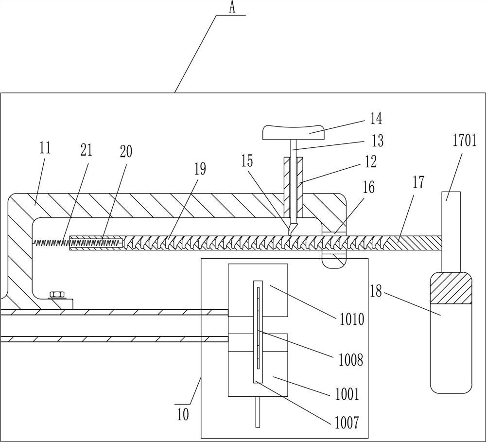
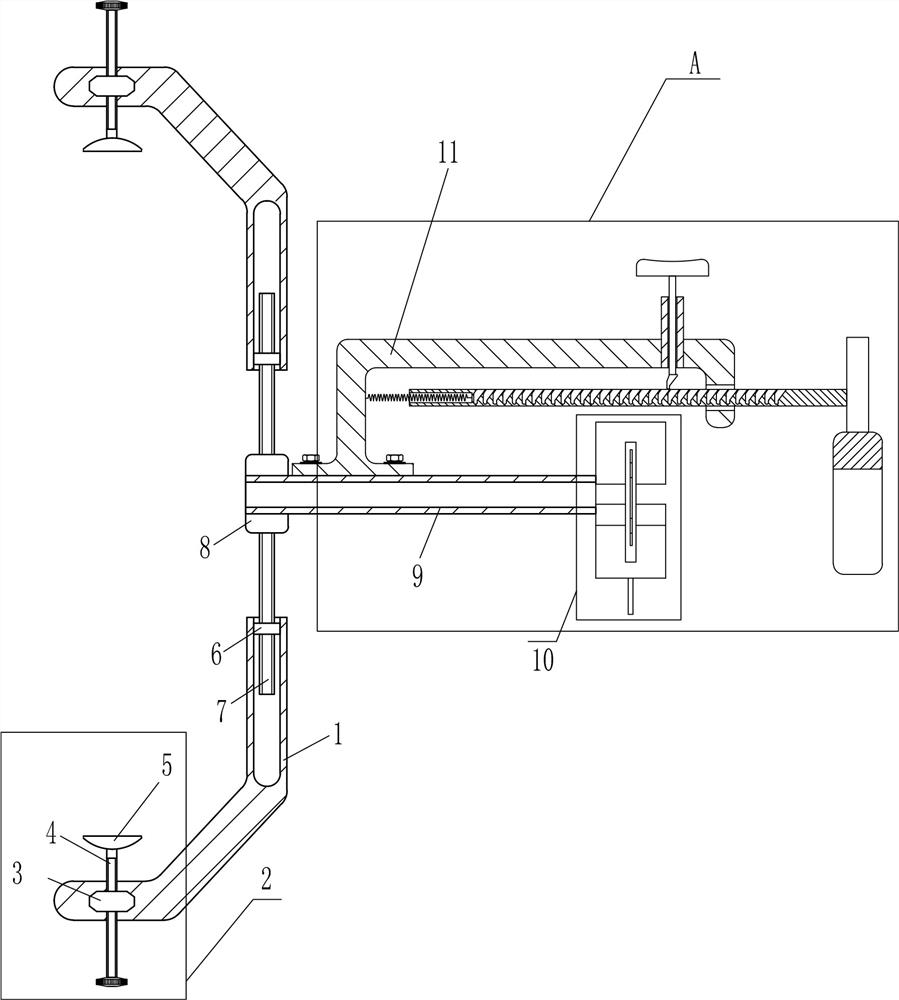
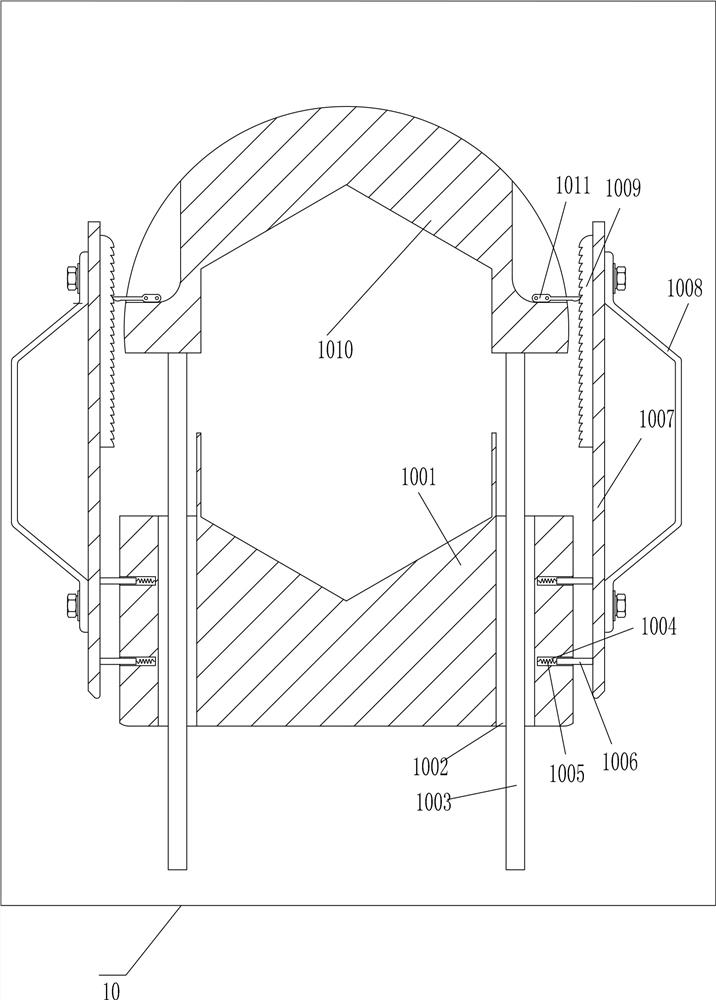
[0014] An auxiliary dismantling device for mold oil pipe joints, such as Figure 1-2 As shown, it includes a curved frame 1, a second nut 6, a second screw rod 7, a first fixed plate 8, an arc sleeve 9, a clamping device 10, a bracket 11, a guide sleeve 12, a first guide rod 13, a stopper Plate 14, wedge-shaped iron block 15, second guide rod 17, vertical rod 1701, U-shaped sleeve 18 and first spring 21, first fixed plate 8 both sides are provided with second screw rod 7, first fixed plate 8 passes through The mode of welding connection is connected with the second screw rod 7, the second screw rod 7 is threadedly connected with the second nut 6, the second nut 6 on the upper and lower sides is symmetrically provided with a curved frame 1, and the front side of the first fixed plate 8 is provided with The arc sleeve 9, the first fixed plate 8 is connected with the arc sleeve 9 by welding, the right side of the arc sleeve 9 is provided with a clamping device 10, the left side o...
Embodiment 2
[0016] An auxiliary dismantling device for mold oil pipe joints, such as Figure 1-3 As shown, it includes a curved frame 1, a second nut 6, a second screw rod 7, a first fixed plate 8, an arc sleeve 9, a clamping device 10, a bracket 11, a guide sleeve 12, a first guide rod 13, a stopper Plate 14, wedge-shaped iron block 15, second guide rod 17, vertical rod 1701, U-shaped sleeve 18 and the first spring 21, the first fixed plate 8 upper and lower sides are all provided with second screw rod 7, on the second screw rod 7 pass The second nut 6 is threaded, and the upper and lower sides of the second nut 6 are symmetrically provided with a curved frame 1, and the front side of the first fixed plate 8 is provided with an arc-shaped sleeve 9, and the right side of the arc-shaped sleeve 9 is provided with a clamping device 10 The left side of the arc cover 9 top is provided with a bracket 11, the right side of the bracket 11 is provided with a guide sleeve 12, the guide sleeve 12 is...
Embodiment 3
[0019] An auxiliary dismantling device for mold oil pipe joints, such as Figure 1-3 As shown, it includes a curved frame 1, a second nut 6, a second screw rod 7, a first fixed plate 8, an arc sleeve 9, a clamping device 10, a bracket 11, a guide sleeve 12, a first guide rod 13, a stopper Plate 14, wedge-shaped iron block 15, second guide rod 17, vertical rod 1701, U-shaped sleeve 18 and the first spring 21, the first fixed plate 8 upper and lower sides are all provided with second screw rod 7, on the second screw rod 7 pass The second nut 6 is threaded, and the upper and lower sides of the second nut 6 are symmetrically provided with a curved frame 1, and the front side of the first fixed plate 8 is provided with an arc-shaped sleeve 9, and the right side of the arc-shaped sleeve 9 is provided with a clamping device 10 The left side of the arc cover 9 top is provided with a bracket 11, the right side of the bracket 11 is provided with a guide sleeve 12, the guide sleeve 12 is...
PUM
 Abstract
Description
Claims
Application Information
 - R&D
- Intellectual Property
- Life Sciences
- Materials
- Tech Scout
- Unparalleled Data Quality
- Higher Quality Content
- 60% Fewer Hallucinations
Browse by: Latest US Patents, China's latest patents, Technical Efficacy Thesaurus, Application Domain, Technology Topic, Popular Technical Reports.
© 2025 PatSnap. All rights reserved.Legal|Privacy policy|Modern Slavery Act Transparency Statement|Sitemap|About US| Contact US: help@patsnap.com