Die lifting-pulling device for self-insulating building block

A self-insulating block and lifting device technology, which is applied in the direction of unloading devices, manufacturing tools, ceramic molding machines, etc., can solve the unreasonable structural design of the lifting device, low mold production efficiency, and affect the production quality of self-insulating blocks Efficiency and other issues

Pending Publication Date: 2019-03-08
中创环能建材科技有限公司
View PDF0 Cites 0 Cited by
  • Summary
  • Abstract
  • Description
  • Claims
  • Application Information

AI Technical Summary

Problems solved by technology

[0002] Most of the molds used in the existing self-insulating block production line are single-group molds, which are used on the single-group mold production line, and the molds are set on the rails and transported forward to the next process for demoulding. It takes a certain amount of time for the thermal insulation block to foam and solidify, so staying on a fixed-length rail leads to low production efficiency of this mold. These are problems that affect the quality and efficiency of self-insulation block production and need to be solved urgently
Double sets of molds can increase the storage capacity of self-insulating blocks on the track, but self-insulating block molds need to design a special lifting device to separate the body from the mold, and the existing lifting device structure design is not reasonable enough, and Generally, it is set for a single group of molds
Therefore, the lack of a special lifting device for double-set molds is a technical problem that needs to be solved at present

Method used


Image

  • Die lifting-pulling device for self-insulating building block
  • Die lifting-pulling device for self-insulating building block
  • Die lifting-pulling device for self-insulating building block

Examples


Embodiment Construction

[0016] In order to make the technical solutions and advantages of the present invention clearer, the present invention will be further described in detail below in conjunction with the accompanying drawings and embodiments.

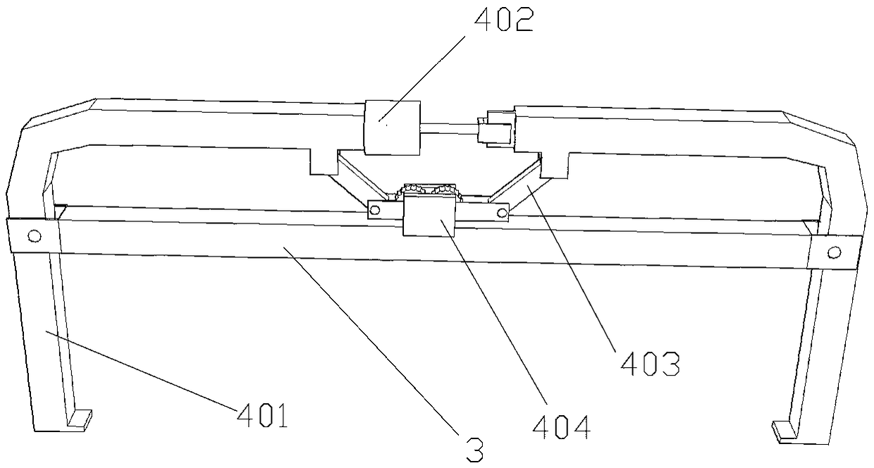
[0017] As shown in the figure: a mold lifting device for self-insulating blocks, including a main frame 1, a mobile frame 2 installed in the main frame 1, and a lifting frame 3 installed on the mobile frame 2, used for Drive the traveling mechanism that the mobile frame 2 advances on the main frame 1 and the lifting mechanism that is used to drive the lifting frame 3 to go up and down on the mobile frame 2 .

[0018] The main frame 1 is a cuboid structure, and two slide rails 101 are arranged in parallel on the upper frame of the main frame 1, and the mobile frame 2 is installed on the slide rails 101, and a plurality of A slide bar mechanism 201, the slide bar mechanism 201 includes a slide bar and a sliding sleeve that is slidably sleeved on the slide b...


PUM


Abstract

The invention discloses a die lifting-pulling device for a self-insulating building block. The die lifting-pulling device comprises a main rack, a moving rack mounted in the main rack, a lifting framemounted on the moving rack, a travelling mechanism used for driving the moving rack to move forward on the main rack, and a lifting mechanism used for driving the lifting frame to rise and fall on the moving rack; the main rack is of a cuboid structure, two sliding rails are parallelly arranged on an upper frame of the main rack, the moving rack is mounted at the sliding rails, and the lifting rack is provided with a plurality of sets of lifting-pulling mechanisms, the multiple sets of lifting-pulling mechanisms are arranged in sequence side by side in the length direction of the sliding rails, the lifting-pulling mechanisms comprise two oppositely-arranged clamping arms, an air cylinder is arranged between the two clamping arms, and inwards-protruding hanging teeth are arranged at the outer ends of the clamping arms. The die lifting-pulling device is specially designed for two sets of forming dies, is easy and convenient to operate, simple in structure, convenient to maintain, and suitable for a self-insulating building block production line of the two sets of side-by-side forming dies.

Description

technical field [0001] The invention belongs to the technical field of self-insulating block production, and in particular relates to a mold lifting device for self-insulating blocks. Background technique [0002] Most of the molds used in the existing self-insulating block production line are single-group molds, which are used on the single-group mold production line, and the molds are set on the rails and transported forward to the next process for demoulding. It takes a certain amount of time for the thermal insulation block to foam and solidify, so staying on a fixed-length rail leads to low production efficiency of the mold, which is an urgent problem that affects the production quality and efficiency of the self-insulation block. Double sets of molds can increase the storage capacity of self-insulating blocks on the track, but self-insulating block molds need to design a special lifting device to separate the body from the mold, and the existing lifting device structur...

Claims


Application Information

Patent Timeline
IPC IPC(8): B28B1/50B28B13/06
CPCB28B1/50B28B13/065
Inventor 李孝武陈献海李光耀
Owner 中创环能建材科技有限公司
Why Eureka
Try Eureka