Transmission shaft front section straightening mechanism adopting circlip groove to position

A technology of circlip grooves and drive shafts, applied in the field of drive shafts, can solve problems such as spline fit errors, middle fork position errors, and overall runout that do not meet the requirements, so as to meet the requirements of guaranteed runout, real alignment effect, and improvement of actual The effect of mass effect

Pending Publication Date: 2019-03-08
WANXIANG QIANCHAO TRANSMISSION SHAFT +1
View PDF7 Cites 0 Cited by
  • Summary
  • Abstract
  • Description
  • Claims
  • Application Information

AI Technical Summary

Problems solved by technology

Since the above-mentioned center hole is only the process reference of the spline shaft and welding fork, plus the spline fit error and the middle fork position error, even if the technical plan is corrected to the range of process requirements, the entire transmission shaft is assembled. After that, the overall beating still does not meet the requirements

Method used


Image

  • Transmission shaft front section straightening mechanism adopting circlip groove to position
  • Transmission shaft front section straightening mechanism adopting circlip groove to position
  • Transmission shaft front section straightening mechanism adopting circlip groove to position

Examples


Embodiment

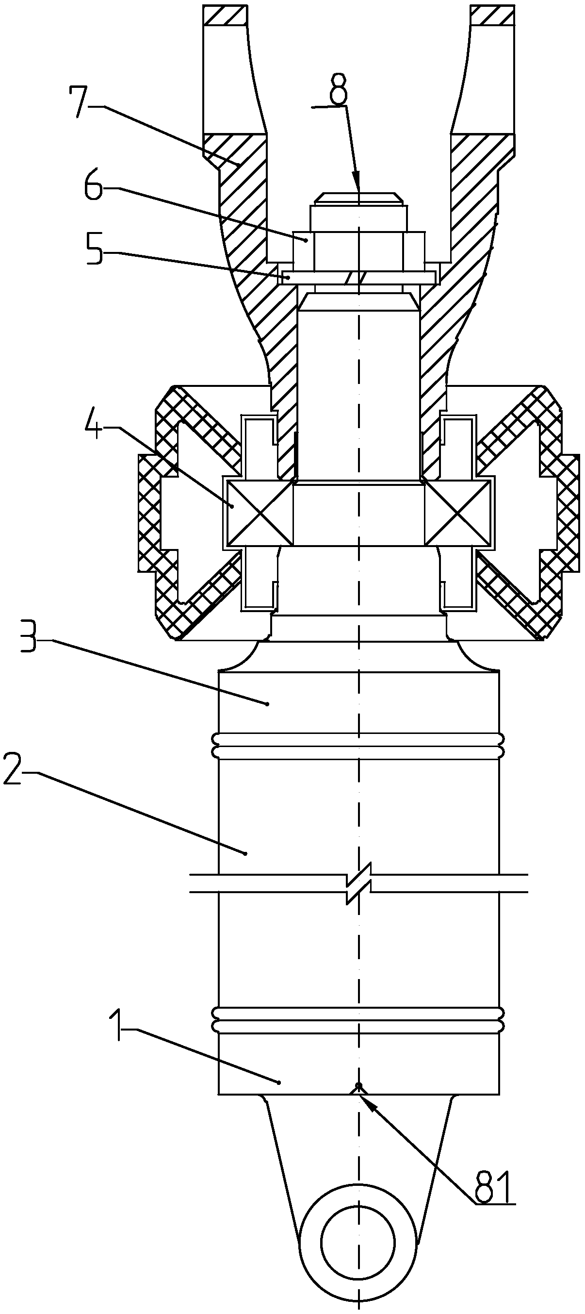
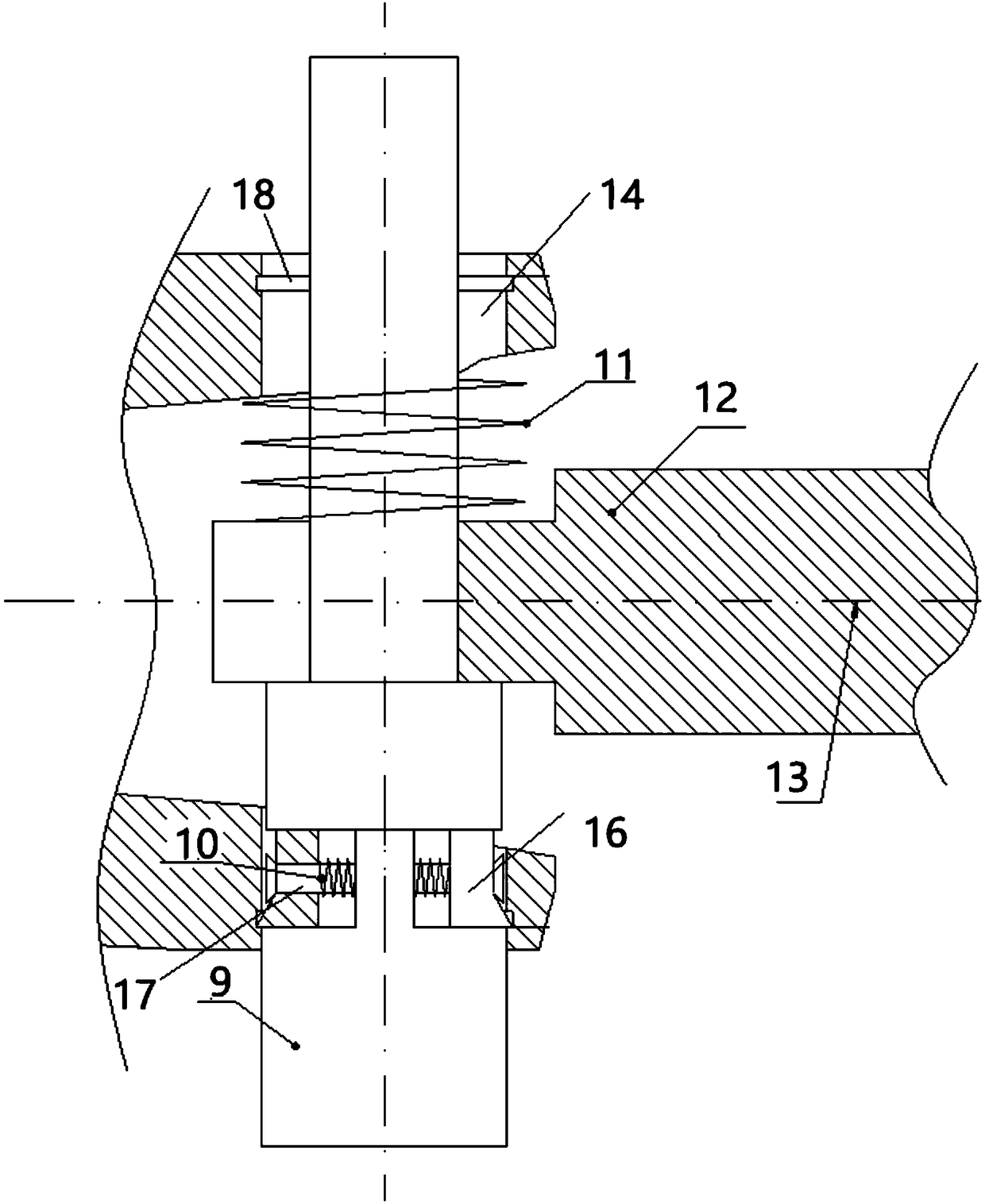
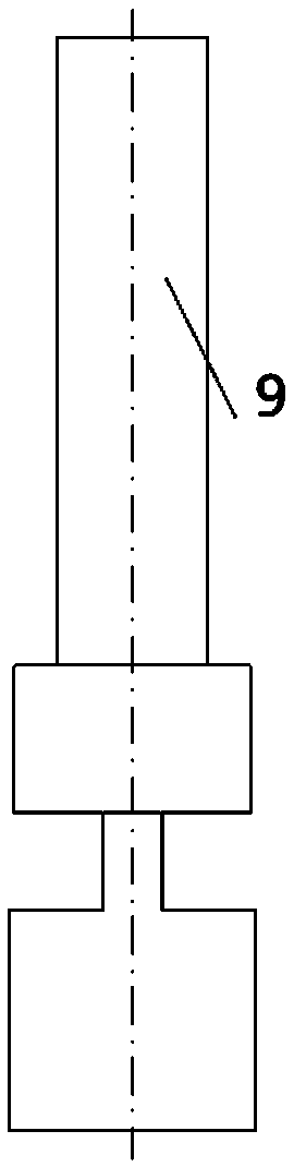
[0016] Embodiment: As shown in the accompanying drawings, the straightening mechanism of the front section of the transmission shaft positioned by the circlip groove mainly includes the mandrel assembly 9, the spring A10, the spring B11, the rotary shaft 12, the ear hole 14, the round hole 15, the tension The opening mechanism 16, the connecting rod 17, the snap ring groove 18, the mandrel assembly 9 is inserted into the ear hole 14, the middle part of the mandrel assembly 9 is inserted into the rotary shaft 12, and a spring B11 is set between the top of the rotary shaft 12 and the ear hole 14 and is set on the core. Outside the rod assembly 9, the mandrel assembly 9 is composed of three sections of cylinders, the top section of the cylinder at the bottom is provided with a platform, and the center of the platform is provided with a circular hole 15. The round hole 15 passes through the connecting rod 17 and the opening mechanism 16 is installed through the connecting rod 17. T...


PUM


Abstract

The invention discloses a transmission shaft front section straightening mechanism adopting a circlip groove to position. The straightening mechanism mainly comprises a core rod assembly, a spring A,a spring B, a rotary shaft, a lughole, a round hole, an opening mechanism, a connecting rod and the circlip groove; the core rod assembly is inserted into the lughole, the rotary shaft is inserted into the middle of the core rod assembly, the spring B is arranged between the upper portion of the rotary shaft and the lughole and is arranged outside the core rod assembly in a sleeving mode, the round hole is formed in a platform below the core rod assembly, the connecting rod penetrates through the round hole, the opening mechanism is arranged through the connecting rod, and the opening mechanism is opened and embedded into the circlip groove in the lughole through the spring A which is arranged outside the connecting rod in a sleeving mode. According to the straightening mechanism, a welding fork and the middle fork lughole circlip groove are directly used as a positioning reference, a design reference is directly used as a straightening reference for straightening, and thus the straightening effect is more real, and the transmission and accumulative errors of parts are avoided; and the actual quality effect of the straightening process is improved, the beating requirement of a wholly assembled transmission shaft is guaranteed, and the overall quality of the transmission shaft is improved.

Description

technical field [0001] The invention relates to the field of transmission shafts, in particular to a front joint straightening mechanism of a transmission shaft positioned by a circlip groove. Background technique [0002] The existing straightening scheme of the front section of the transmission shaft is to use the center hole of the welding fork and the center hole of the spline shaft for positioning, and then use the straightening equipment to correct the runout T of the shaft tube to the range of the process requirements. Since the above-mentioned center hole is only the process reference of the spline shaft and welding fork, plus the spline fit error and the middle fork position error, even if the technical plan is corrected to the range of process requirements, the entire transmission shaft is assembled. After that, the overall beating still does not meet the requirements. Contents of the invention [0003] The purpose of the present invention is to overcome the def...

Claims


Application Information

Patent Timeline
Patent Type & Authority Applications(China)
IPC IPC(8): B21D3/14B21D3/16
CPCB21D3/14B21D3/16
Inventor 陈龙
Owner WANXIANG QIANCHAO TRANSMISSION SHAFT
Why Eureka
Try Eureka