Fluid pump and method for assembling fluid pump

The technology of a fluid pump and main body is applied to the components of the pumping device for elastic fluid, the pump device, the pump, etc., to achieve the effect of reducing the production cost and reducing the production effort.

Active Publication Date: 2019-03-05
MAHLE INT GMBH
View PDF13 Cites 2 Cited by
  • Summary
  • Abstract
  • Description
  • Claims
  • Application Information

AI Technical Summary

Problems solved by technology

Also, the control board must be properly adjusted when making any modifications to the electric motor

Method used


Image

  • Fluid pump and method for assembling fluid pump
  • Fluid pump and method for assembling fluid pump
  • Fluid pump and method for assembling fluid pump

Examples


Embodiment Construction

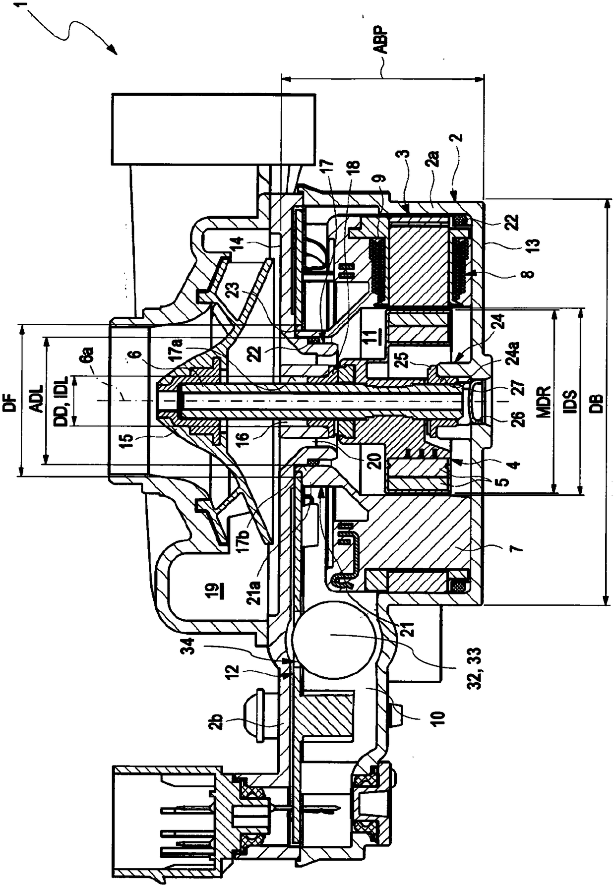
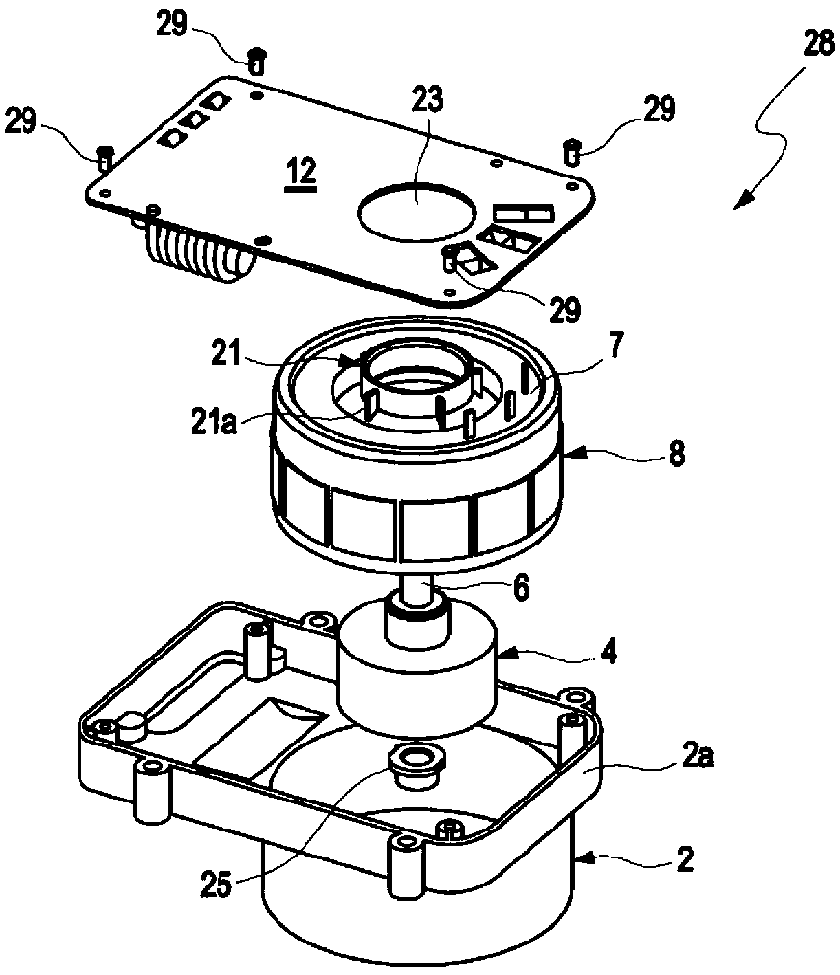
[0028] figure 1 A sectional view of an electric fluid pump 1 according to the invention is shown. The fluid pump 1 has a pump housing 2 and an electric motor 3 arranged in the pump housing 2 . The pump housing 2 is formed in this case by a housing bottom 2 a and a housing cover 2 b. A rotor 4 with permanent magnets 5 is fixed for common rotation to a rotor shaft 6 and is mounted in a stator body 7 with an embedded stator 8 so as to be rotatable about an axis of rotation 6a. The stator 8 has a plurality of coils 9 and other electronic components embedded in the stator body and surrounded by the material of the stator body 7 (eg plastic). In this way, the coils 9 and other electronic components of the stator 8 can be protected from the fluid to be pumped. The stator body 8 is surrounded by a part-cylindrical housing bottom 2a, so that the heat generated in the stator body 7 can be dissipated to the outside. For this purpose, the housing bottom 2a can be made of aluminum, for...


PUM


Abstract

The invention relates to an electric fluid pump which may include a pump housing and an electric motor arranged therein. A rotor of the electric motor may have a rotor shaft and may be mounted in a rotatable manner in a stator body, which may have a stator embedded at least regionally therein. The pump housing may be subdivided into a dry region and a wet region containing the rotor. The rotor shaft may be mounted on a bottom side in the pump housing and may project out of an aperture on a pump-impeller side facing away from the bottom side. In addition, the rotor shaft may be connected in terms of drive to a pump impeller. According to the invention, the pump housing may have an internal first bearing collar arranged around the aperture, wherein the dry region may be located radially around the first bearing collar, and wherein an outside diameter of the first bearing collar may be less than a maximum diameter of the rotor. The invention also relates to a method for assembling the fluid pump.

Description

technical field [0001] The invention relates to an electric fluid pump according to the preamble of claim 1 . The invention also relates to a method for assembling a fluid pump. Background technique [0002] An electric fluid pump is known, for example, from DE 10 2012 222 358 A1 and is used for conveying fluids. In this case, the fluid pump usually has a housing and an electric motor arranged in the housing. In this case, the electric motor includes a stator and a rotor rotatably mounted in the stator. In order to protect the stator from the fluid to be pumped, the stator is arranged in a split housing or embedded in the stator body. The stator body then usually also forms the housing of the fluid pump. In this way, the fluid pump is divided into two areas. In the wet area located inside the stator, the fluid to be pumped flows and at the same time cools the rotor. In the dry area located around the stator body, the control board is usually secured through openings ar...

Claims


Application Information

Patent Timeline
Patent Type & Authority Applications(China)
IPC IPC(8): F04D13/06F04D29/04F04D29/40F04D29/58F04D29/60
CPCF04D13/06F04D29/04F04D29/406F04D29/5806F04D29/586F04D29/5893F04D29/605F04D13/0633F04D13/0686F04D29/588F04D13/0626F04D13/0613F04D29/5813F04D29/026F04D13/0653F04D29/426F04D29/628
Inventor J·迪克曼A·卢尔B·维曼
Owner MAHLE INT GMBH
Why Eureka
Try Eureka