


Quick Research
Generate reliable direction feasibility study reports for your R&D in just a few steps.

Technical Q&A
Discover and master advanced knowledge NOW. Basics, ideas, possibilities, all at once.

Find Solutions
As an expert in R&D theories, this can generate solutions to your technical problems instantly.

Evaluate Feasibility
Analyze your overall solution with one click, know your potential R&D risks in advance.

Monitor Landscape
Get weekly tech updates, stay abreast of the latest tech innovations and key insights.
Novel net sheet-like winding-unwinding equipment
A rewinding and unwinding, sheet-like technology, applied in the field of new mesh-like rewinding and unwinding equipment, can solve problems such as uneven movement, and achieve the effects of stable operation, reduced resistance and long service life
- Summary
- Abstract
- Description
- Claims
- Application Information
AI Technical Summary
Problems solved by technology
Method used
Image

Examples
specific Embodiment approach 1
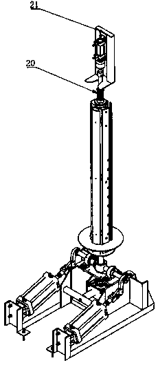
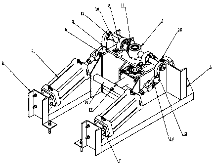
[0024] Specific implementation mode one: combine figure 1 -. As shown, it includes a winding base 1, a large cylinder 2, a rotary seat 3 and a main shaft 4; one end of the winding base 1 is provided with two positioning plates 5 in parallel, and the other end is provided with two supporting plates 6 in parallel; A fixed seat 7 is arranged on the straight plane; the fixed seat 7 is connected with the rotating shaft at one end of the large cylinder 2; a U-shaped plate 8 is installed horizontally on the upper end surface of the support plate 6; two bearing seats 9 are uniformly arranged on the upper end surface of the U-shaped plate 8; Two rotating half shafts 10 are welded at the center of the side of seat 3; There is a motor connection frame 11; a square sleeve 12 is installed on the top of the rotating half shaft 10; a rocker arm 13 is welded to the outer ring of the square sleeve 12; a lug 14 is welded to the lower end of the rocker arm 13; Revolving shaft connection; geare...
specific Embodiment approach 2
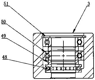
[0026] Specific implementation method two: a second thrust bearing is arranged on the lower part of the slewing seat, and two spacers and two second deep 00 groove ball bearings are placed on the upper axis of the thrust bearing, so that the workpiece on the rewinding shaft can rotate normally within 200kg ;
specific Embodiment approach 3
[0027] Embodiment 3: There is a groove on the fixed plate, and the adjustment tray is carried on the fixed plate through the protruding part, which can be applied to workpieces of different sizes, and one end of the screen can be hung on any groove when the wire mesh is wound. The through hole is matched with the main shaft, the pin shaft of the connecting plate is connected with the movable plate, and the bolt of the connecting block is connected with the fixed plate. When the winding shaft is erected, the movable plate moves downwards and outwards through its own gravity, so that the whole expands, and the wire mesh hangs on the fixed plate. Rewinding at the groove, when the rewinding shaft is laid down and placed horizontally through the large cylinder, the movable plate moves inward to realize shrinkage, so that the whole roll of screen can be withdrawn smoothly. The process of contraction and expansion is realized by the gravity of the movable plate itself. The protruding...
PUM
 Abstract
Description
Claims
Application Information
 - R&D Engineer
- R&D Manager
- IP Professional
- Industry Leading Data Capabilities
- Powerful AI technology
- Patent DNA Extraction
Browse by: Latest US Patents, China's latest patents, Technical Efficacy Thesaurus, Application Domain, Technology Topic, Popular Technical Reports.
© 2024 PatSnap. All rights reserved.Legal|Privacy policy|Modern Slavery Act Transparency Statement|Sitemap|About US| Contact US: help@patsnap.com