Split structure for dry magnetically controlled reactor shell

A magnetron reactor, dry-type technology, applied in the direction of transformer/inductor shell, etc., can solve the problems of damage to the overall frame structure, high cost, lack of penetration, etc., to improve the reliability of connection, good use effect, and high stability. Effect

Inactive Publication Date: 2019-03-01
江苏华峰电器控制设备有限公司
View PDF1 Cites 0 Cited by
  • Summary
  • Abstract
  • Description
  • Claims
  • Application Information

AI Technical Summary

Problems solved by technology

[0002] The low pressure of the general shell frame is a combined structure, the basic frame is assembled by C-shaped steel, and the welding technology is used as a metal closed box structure. The cabinet is fixed and installed, and it is welded by angle steel and thin steel plate. Welding method, there is always welding residual stress after welding, but the residual stress of different methods is different. Due to the rapid cooling of the heat-affected zone, the welded parts are prone to cracks under the condition of high carbon content, which will cause the overall frame The structure is damaged, and the welding process is not well controlled, and defects such as pores, slag inclusions, incomplete fusion, and incomplete penetration are likely to occur, which makes the overall frame shell poor in stability, high in cost, and cannot be transported over long distances. It is difficult for small and medium-sized users
[0003] The Chinese utility model patent with the patent number "201620918134.6" provides a magnetically controlled reactor shell frame, which adopts a screwed and riveted structure and has no thermal stress. The columns are all made of ordinary steel plates, and they are only connected by screws. The splicing structure is simple, and the strength of the joints is often not good. It cannot have good strength and the connection reliability is not good.

Method used


Image

  • Split structure for dry magnetically controlled reactor shell
  • Split structure for dry magnetically controlled reactor shell
  • Split structure for dry magnetically controlled reactor shell

Examples


Embodiment Construction

[0021] In order to make the technical solution of the present invention clearer, the present invention will be further described below in conjunction with the accompanying drawings. Any solution obtained by equivalent replacement and conventional reasoning of the technical features of the technical solution of the present invention falls within the protection scope of the present invention. The fixed connection mentioned in this embodiment, the fixed arrangement and the fixed structure are all screw connections, bolt and nut connections.

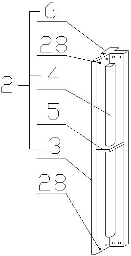
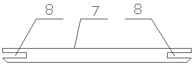
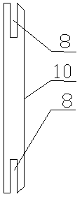
[0022] A splicing structure of a dry-type magnetron reactor shell, characterized in that it includes a column, a beam and a longitudinal beam; the number of the columns is 4, and the columns are an integrated structure, including a column body and an inner reinforcing protrusion And the outer reinforcement protrusion, the column body is L-shaped steel structure, the inner reinforcement protrusion is a quarter cylindrical structure, the inner ...


PUM


Abstract

The invention discloses a split structure for a dry magnetically controlled reactor shell. The split structure comprises stand columns, crossbeams and longitudinal beams, wherein each stand column comprises a stand column body, an inner reinforced bulge and an outer reinforced bulge; two ends of each crossbeam and two ends of each longitudinal beam are independently provided with a clamping grooveof a square groove structure; the crossbeams and the longitudinal beams are inserted into the clamping grooves from two sides of the top and the bottom of each stand column body; and a screw hole onone side of each clamping groove and screw holes on two sides of each stand column body are cooperated with bolts to realize fixed connection. When the split structure is used, by use of the special crossbeam, longitudinal beam and stand column structure, each stand column adopts an internal and external dual reinforced bulge structure, and the strength of the stand column can be greatly improved.During connection, the special stand column structures are cooperated, each crossbeam and each longitudinal beam are independently provided with the clamping groove. During connection, by use of thespecially designed split structure, two ends of each stand column body can be embedded in the clamping grooves and are then connected through the bolts. By use of the structure, the strength of the junction can be effectively guaranteed.

Description

technical field [0001] The invention belongs to the field of electrical equipment, in particular to a splicing structure of a dry-type magnetron reactor shell. Background technique [0002] The low pressure of the general shell frame is a combined structure, the basic frame is assembled by C-shaped steel, and the welding technology is used as a metal closed box structure. The cabinet is fixed and installed, and it is welded by angle steel and thin steel plate. Welding method, there is always welding residual stress after welding, but the residual stress of different methods is different. Due to the rapid cooling of the heat-affected zone, the welded parts are prone to cracks under the condition of high carbon content, which will cause the overall frame The structure is damaged, and if the control is not in place during the welding process, defects such as pores, slag inclusions, incomplete fusion, and incomplete penetration are likely to occur, which makes the overall frame ...

Claims


Application Information

Patent Timeline
Patent Type & Authority Applications(China)
IPC IPC(8): H01F27/02
CPCH01F27/02
Inventor 朱学林朱频萍
Owner 江苏华峰电器控制设备有限公司
Why Eureka
Try Eureka