
Horizontal axial wind following high-speed rotation wind power generator

A technology of wind generators and high-speed rotation, which is applied to wind turbines, wind turbines, and wind motor combinations in the same direction as the wind, and can solve problems such as loose slotting at the end of the gearbox, poor utilization of wind energy, and hidden dangers to personal safety.

Inactive Publication Date: 2019-03-01
XIANGSHAN HONGQIANG ELECTRIC MFG CO LTD
View PDF6 Cites 3 Cited by
  • Summary
  • Abstract
  • Description
  • Claims
  • Application Information

AI Technical Summary

Problems solved by technology

[0004] Aiming at the deficiencies in the prior art, the purpose of the present invention is to provide a high-speed rotating wind generator that follows the wind horizontally and axially to solve the problem that the blades of the windmill cannot be oriented to follow the change of the wind direction and rotate. When the wind force is too strong, the outer end of the inner shaft is affected by the external The blades and the wind drive will produce shaking, which will easily loosen the gear box connection inside the equipment for a long time. At the same time, it will also cause the blade yaw to be unable to rotate around the center line of the tower. The utilization rate of wind energy is poor, and maintenance is difficult. Time-consuming, there is a problem of personal safety hazards

Method used


Image

  • Horizontal axial wind following high-speed rotation wind power generator
  • Horizontal axial wind following high-speed rotation wind power generator
  • Horizontal axial wind following high-speed rotation wind power generator

Examples


Embodiment Construction

[0023] In order to make the technical means, creative features, goals and effects achieved by the present invention easy to understand, the present invention will be further described below in conjunction with specific embodiments.

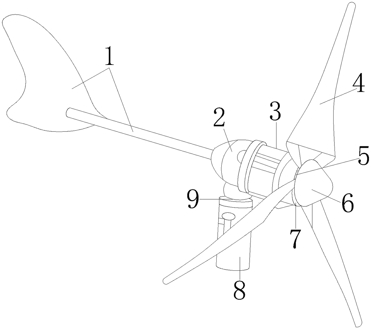
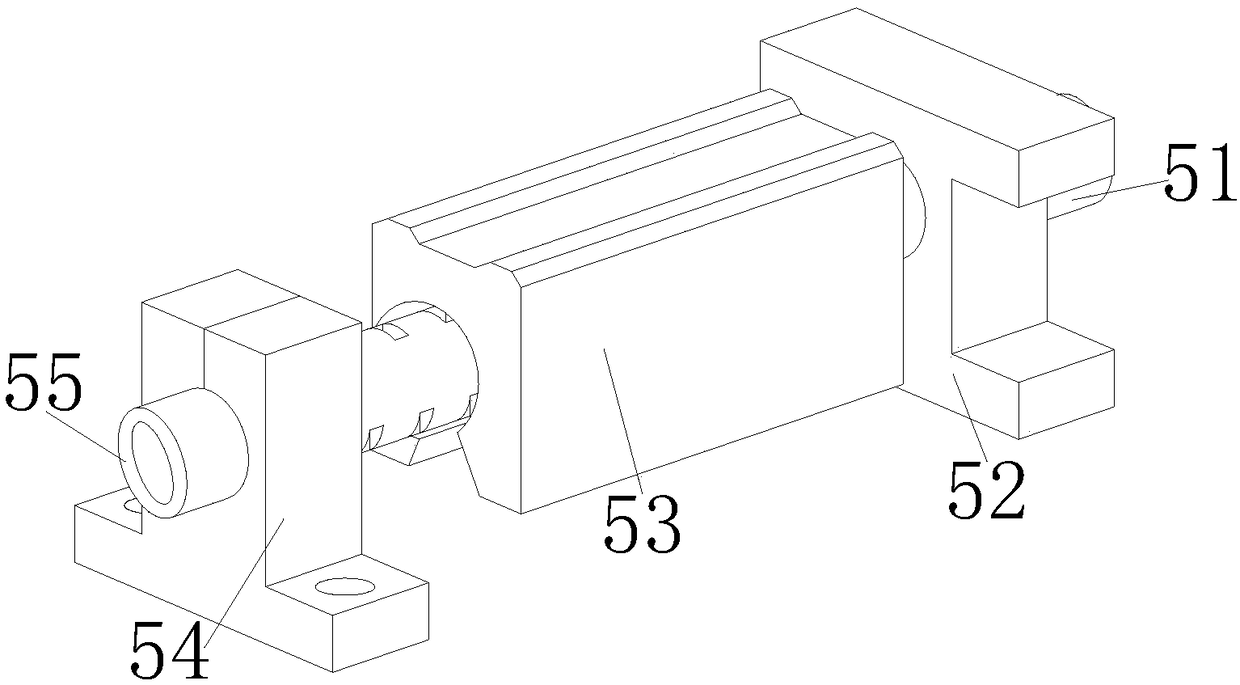
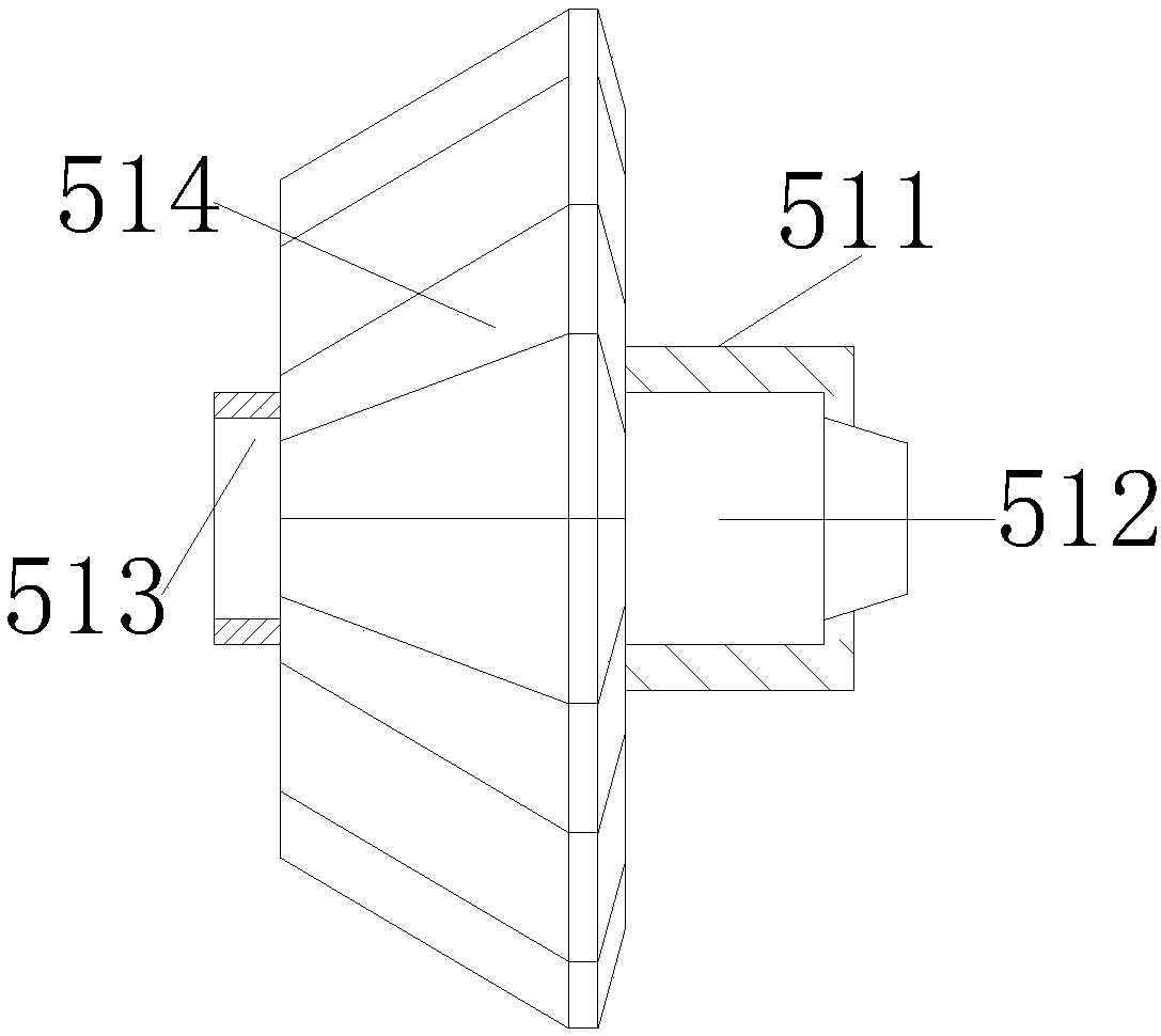
[0024] see Figure 1-Figure 7 , the present invention provides a high-speed rotating wind generator with a horizontal axis following the wind, its structure includes an empennage 1, a generator 2, a nacelle shell 3, a windmill blade 4, a blade navigation mechanism 5, a shroud 6, a hub 7, and a tower 8. The rotary shaft 9, the empennage 1 is horizontally installed in the center of the rear end of the nacelle shell 3 and is fixedly connected, and the inner rear of the nacelle shell 3 is provided with a generator 2 for fastening and buckling connection, and the windmill blades 4 are distributed and arranged around the guide The outer wall of the flow cover 6 is equally spaced, and the front end of the blade navigation mechanism 5 is fastened and embe...


PUM


Abstract

The invention discloses a horizontal axial wind following high-speed rotation wind power generator. The horizontal axial wind following high-speed rotation wind power generator structurally comprisesa tail wing, a power generator body, a cabin shell, windmill blades, a blade navigation mechanism, a fairing, a hub, a tower frame and a rotation shaft. Through installation and connection of the front end of a main direction shaft and an inner rod of the fairing, the main direction shaft follows rotation when the windmill blades are pushed by wind, an inner rotation rod and the main direction shaft can stably do the rotation movement through an insert at the time; meanwhile, an outer barrel directionally overturns through cooperation of equal-distance groove holes in the edge wall and obliqueteeth on the surface of a double-face winch, a retainer in an intermediate joint is used for conducting forward pushing, the main direction shaft rolls back and forth through fine balls so that an outer gear can be driven to accelerate to twist the integral mechanical power of a shaft piece in a gear case, the equipment can sufficiently utilize wind energy for volatilization, the blade rolling speed is increased, rapid power generation is conducted, and if the wind direction changes and reverse running happens, a spiral winch rod can brake the main direction shaft through the outer wall double-face winch, and the situation that the outer end of an inner shaft reversely rotates and is fractured or the gear case is damaged is prevented.

Description

technical field [0001] The invention relates to a high-speed rotating wind generator capable of following the wind horizontally and axially, and belongs to the technical field of wind power generation. Background technique [0002] Wind power generators convert wind energy into mechanical work through the blades, and then increase the rotation speed through the speed increaser to drive the generator to generate electricity. The utilization rate of wind energy is high, which greatly saves resources and energy, and has zero carbon emissions and does not pollute the environment. There are following deficiencies: [0003] The blades of the windmill cannot be oriented to follow the change of the wind direction to rotate. When the wind force is too strong, the outer end of the inner shaft will vibrate when driven by the external blades and wind force. It is easy to loosen the internal gear box connection of the equipment for a long time, and at the same time As a result, the blad...

Claims


Application Information

Patent Timeline
IPC IPC(8): F03D1/00F03D1/04F03D9/25F03D15/10F03D7/02
CPCF03D1/00F03D1/04F03D7/0248F03D9/25F03D15/10Y02E10/72
Inventor 孙岳明
Owner XIANGSHAN HONGQIANG ELECTRIC MFG CO LTD
Learn More