


Quick Research
Generate reliable direction feasibility study reports for your R&D in just a few steps.

Technical Q&A
Discover and master advanced knowledge NOW. Basics, ideas, possibilities, all at once.

Find Solutions
As an expert in R&D theories, this can generate solutions to your technical problems instantly.

Evaluate Feasibility
Analyze your overall solution with one click, know your potential R&D risks in advance.

Monitor Landscape
Get weekly tech updates, stay abreast of the latest tech innovations and key insights.
Die-cutting laminating machine
A compound machine and die-cutting technology, applied in lamination device, lamination auxiliary operation, lamination and other directions, can solve the problems of affecting the collection of finished waste, slippage, inconvenient connection of staff, etc.
- Summary
- Abstract
- Description
- Claims
- Application Information
AI Technical Summary
Problems solved by technology
Method used
Image

Examples
Embodiment 1
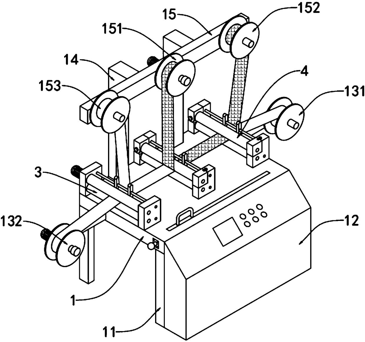
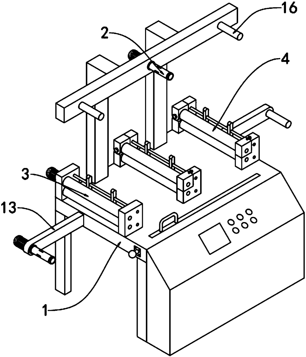
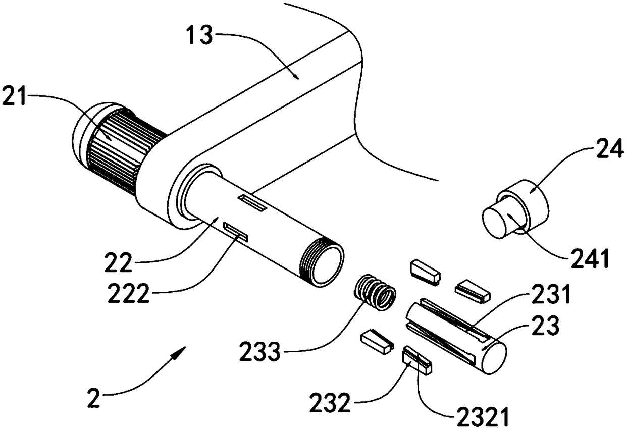
[0034] A die-cut compound machine, such as figure 1 , figure 2 , image 3 and Figure 4 As shown, including the compound machine body 1, the four corners of the bottom end of the compound machine body 1 are provided with support legs 11, the front end of the compound machine body 1 is provided with a control room 12, and the left and right edges of the top of the compound machine body 1 side rods 13 are installed at each side, and a connecting rod 14 is installed at the rear side edge of the top of the composite machine body 1, and a cross bar 15 is installed on the top of the connecting rod 14, which is located at the end of the left side rod 13 and in the middle of the cross rod 15 A tightening device 2 is provided at each position.
[0035] In this embodiment, the left edge of the front end of the cross bar 15, the right edge of the front end of the cross bar 15, and the edge of the front end of the right side bar 13 are all equipped with a fixed rod 16, which is locate...
Embodiment 2
[0041] A die-cut compound machine, such as Figure 5 , Figure 6 ,and Figure 7 As shown, a rolling device 3 is provided at the left edge of the top of the composite machine body 1, and a pressing device 4 is provided at the middle position and the right edge of the top of the composite machine body 1, and both the rolling device 3 and the pressing device 4 are A regulating device 5 is installed.
[0042] In this embodiment, the rolling device 3 includes a first mount 31 mounted on the front and rear edges of the compound machine body 1 and a second rotating motor 32 mounted on the first mount 31 at the rear end. The first mount Between 31, driving roller 311 is installed, and driving roller 311 is coaxially connected with the output shaft of second rotating motor 32 and is connected with the rotation of first mounting base 31, and the bottom of driving roller 311 is installed with the first mounting base 31. Rotate the connected driven roller 312, when the power supply of ...
Embodiment 3
[0047] A die-cut compound machine, such as Figure 8 , Figure 9 and Figure 10 As shown, a port 17 is provided at the front edge of the top of the compound machine body 1, and a protective device 6 is installed in the port 17. A cover groove 18 is opened at the front side of the left end of the compound machine body 1, and the cover groove 18 passes The bolt is fixed with a cover plate 181, and the bottom of the cover groove 18 is provided with a counterbore 182, and the bottom of the counterbore 182 is provided with a through hole 183 communicating with the port 17, and the positioning device 7 is installed in the counterbore 182.
[0048] In this embodiment, the protective device 6 includes an outer frame 61 that matches the shape of the opening 17 and a protective net 62 tightly welded on the surface of the outer frame 61. The outer frame 61 is sleeved in the opening 17 and slides with the opening 17. Connection, the upper left end of the outer frame 61 is tightly welded...
PUM
 Abstract
Description
Claims
Application Information
 - R&D Engineer
- R&D Manager
- IP Professional
- Industry Leading Data Capabilities
- Powerful AI technology
- Patent DNA Extraction
Browse by: Latest US Patents, China's latest patents, Technical Efficacy Thesaurus, Application Domain, Technology Topic, Popular Technical Reports.
© 2024 PatSnap. All rights reserved.Legal|Privacy policy|Modern Slavery Act Transparency Statement|Sitemap|About US| Contact US: help@patsnap.com