Broken-filament filtering and separating device for printing and dyeing equipment

A technology of filtration separation, printing and dyeing equipment, applied in filtration separation, separation methods, moving filter element filters, etc., can solve problems such as insufficient filtration, and achieve the effect of firm separation tank, enhanced sealing, and avoidance of sewage seepage

Inactive Publication Date: 2019-02-26
唐海元
View PDF1 Cites 0 Cited by
  • Summary
  • Abstract
  • Description
  • Claims
  • Application Information

AI Technical Summary

Problems solved by technology

[0006] In order to overcome the shortcomings of insufficient filtration in the existing wool filter device, the technical problem to be solved by the invention is to provide a wool filter separation device for printing and dyeing equipment with sufficient filtration

Method used


Image

  • Broken-filament filtering and separating device for printing and dyeing equipment
  • Broken-filament filtering and separating device for printing and dyeing equipment
  • Broken-filament filtering and separating device for printing and dyeing equipment

Examples


Embodiment 1

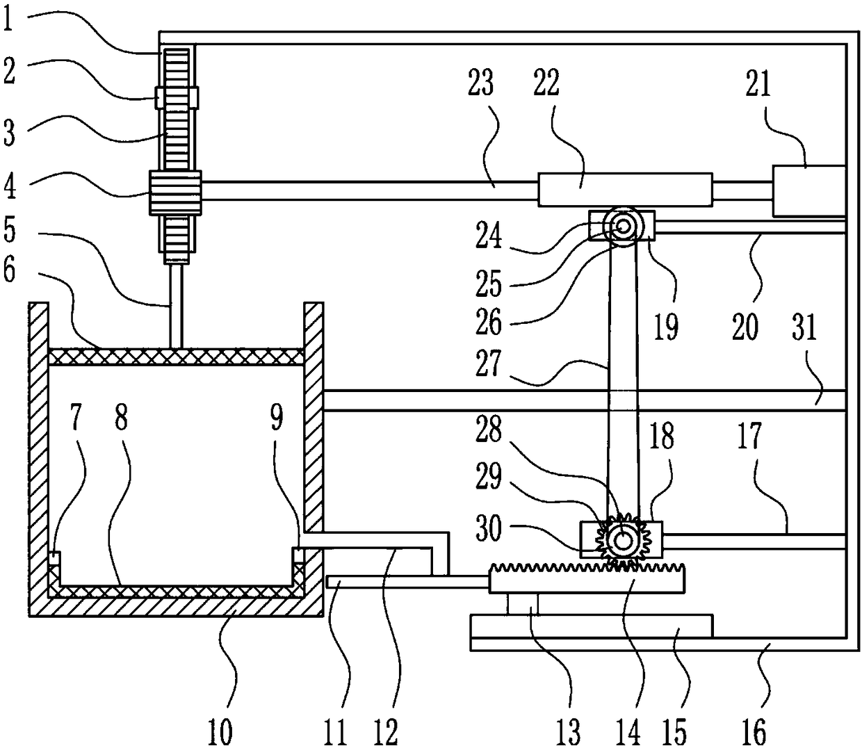
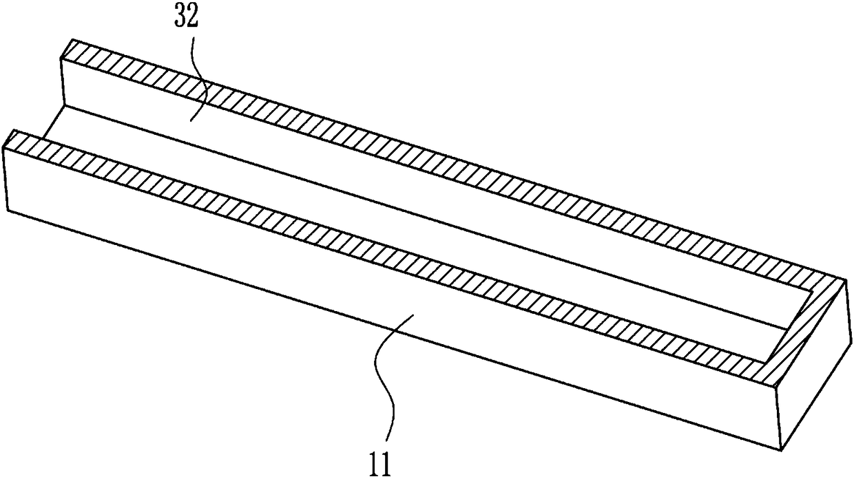
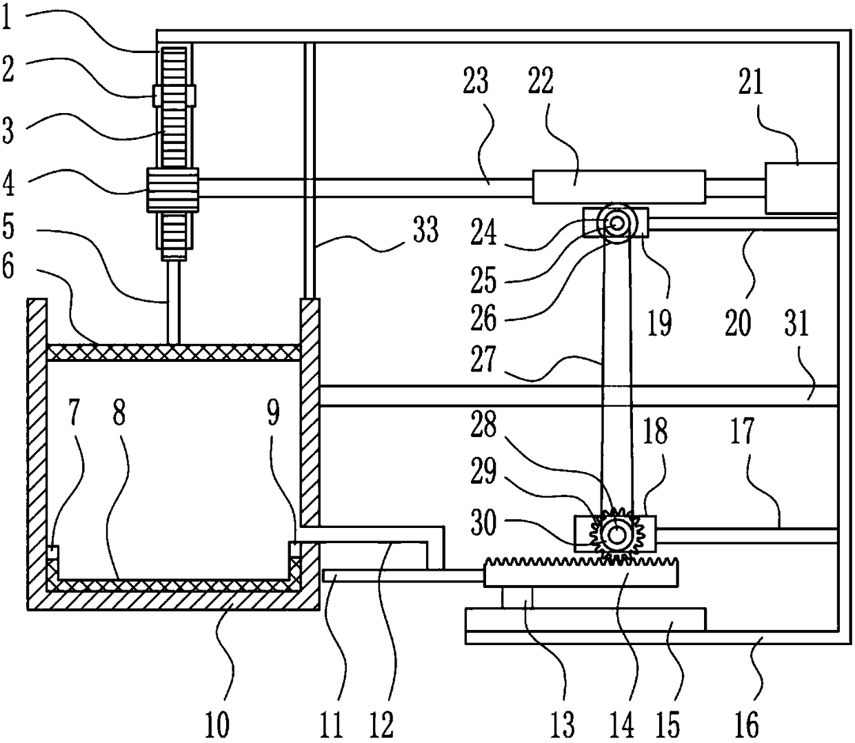
[0037] A wool filter separation device for printing and dyeing equipment, such as Figure 1-6 As shown, it includes the first slide rail 1, the first slider 2, the first rack 3, the first gear 4, the lifting rod 5, the iron filter screen 6, the first magnet 7, the mesh groove 8, the second magnet 9. Separation groove 10, block 11, square water pipe 12, second slider 13, second rack 14, second slide rail 15, bracket 16, lower connecting rod 17, lower bearing seat 18, upper bearing seat 19, Upper connecting rod 20, motor 21, worm screw 22, first rotating shaft 23, small pulley 24, second rotating shaft 25, worm wheel 26, flat belt 27, third rotating shaft 28, second gear 29, large pulley 30 and middle connecting rod 31 The left end of the top of the bracket 16 is welded with a first slide rail 1, the front side of the first slide rail 1 is slidably provided with a first slider 2, and the front side of the first slider 2 is welded with a first rack 3, The bottom of the first rac...


PUM


Abstract

The invention relates to a filtering and separating device, particularly to a broken-filament filtering and separating device for printing and dyeing equipment. To overcome technical problems in the prior art, the invention provides the broken-filament filtering and separating device capable of realizing sufficient filtration. The broken-filament filtering and separating device for printing and dyeing equipment comprises a first sliding rail, a first sliding block, a first rack, a first gear, a lifting rod, an iron filter net, a first magnet, a mesh groove, a second magnet, a separation groove, a stop piece, etc., wherein the first sliding rail is welded onto and connected with the left end of the inner top of a bracket; the first sliding block is slidably arranged on the front side of thefirst sliding rail; the front side of the first sliding block is welded and connected with the first rack; and the bottom of the first rack is welded and connected with the lifting rod. The broken-filament filtering and separating device of the invention achieves the effects of simple structure, ingenious design and sufficient filtering.

Description

technical field [0001] The invention relates to a filtering and separating device, in particular to a wool filtering and separating device for printing and dyeing equipment. Background technique [0002] In the printing and dyeing industry, the dyeing machines used in the textile boiling and bleaching process will produce a large amount of high-temperature sewage during the production process, and the sewage will contain wool, which makes the sewage treatment machine easily blocked. [0003] Chinese patent CN204193623U discloses a new type of printing and dyeing equipment filter and flushing device for the problem of finger filtration, which includes a housing, an upper cover, a rotating impeller device, and a filter screen. Shape, the lower part of the housing is provided with a sewage outlet, the sewage outlet is provided with a rotating bracket, the lower part of the housing is also provided with a bracket, a rotating impeller device is installed in the housing, and a swe...

Claims


Application Information

Patent Timeline
Patent Type & Authority Applications(China)
IPC IPC(8): B01D33/01B01D33/76B01D33/80
CPCB01D33/0158B01D33/76B01D33/801
Inventor 唐海元
Owner 唐海元
Why Eureka
Try Eureka