Vehicle camera with focusing by employing screw rod

A camera and screw technology, applied in the field of vehicle cameras, can solve the problems of blurred images, easy generation of debris, high defect rate, etc., to achieve the effect of ensuring image quality and convenient adjustment

Pending Publication Date: 2019-02-22
SUZHOU INVO AUTOMOTIVE ELECTRONICS
View PDF4 Cites 1 Cited by
  • Summary
  • Abstract
  • Description
  • Claims
  • Application Information

AI Technical Summary

Problems solved by technology

[0002] Existing car cameras, see figure 1 , the back shell e and the front shell d are connected and locked with the compression gasket b through the screw a to realize the waterproof of the front and rear shells, the rear shell e squeezes the inner shell f, the inner shell f squeezes the lens c, and the lens c and the front shell d squeeze The O-ring g is used to realize the waterproofing of the front shell and the lens. Its focal length adjustment method fixes the sensor h and the inner shell f together, so that the lens c and the inner shell f can be adjusted up and down through threads to complete the focus adjustment. Its disadvantages As follows: When the rear shell e presses the inner shell f downward, the inner shell f is deformed by force, which changes the relative distance between the PCBA and the lens, and then causes defocusing, resulting in blurred images, seriously affecting the quality, poor stability, and poor quality. The rate is high; and the torque between the lens c and the inner shell f is difficult to control, debris is easily generated during production, and black spots appear in the image

Method used


Image

  • Vehicle camera with focusing by employing screw rod
  • Vehicle camera with focusing by employing screw rod

Examples


Embodiment Construction

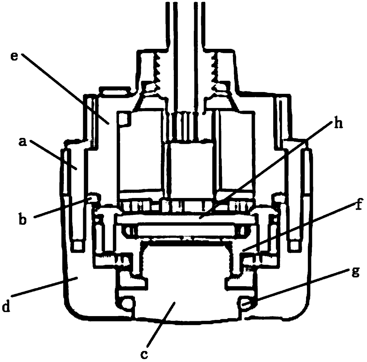
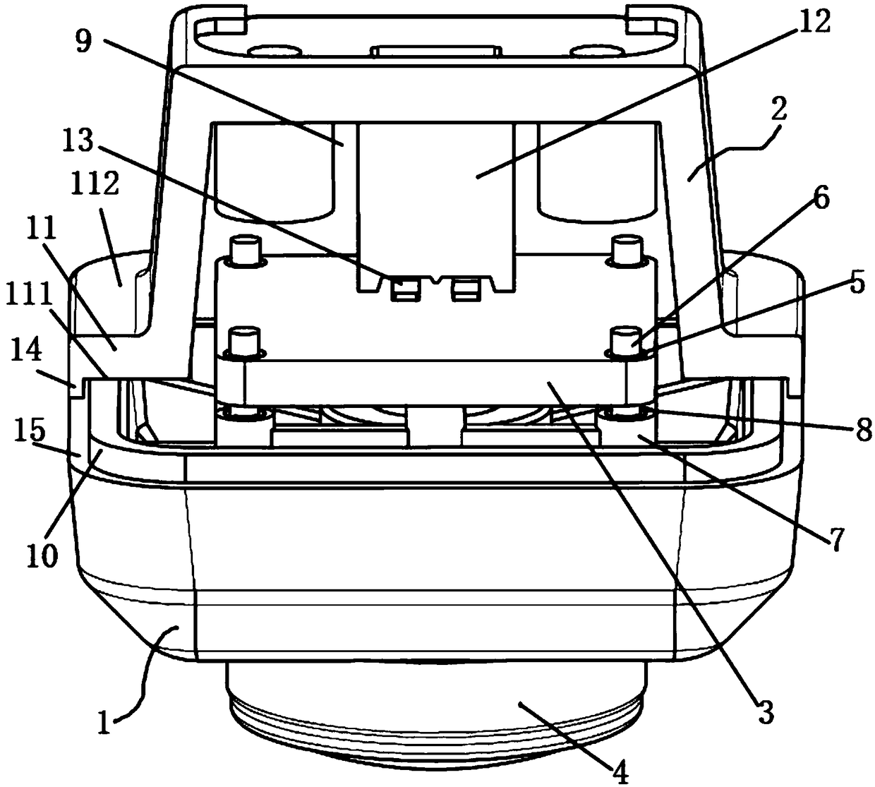
[0017] A screw focus vehicle camera, see figure 2 : it comprises a front shell 1, a rear shell 2, a sensor substrate 3, a camera lens 4, the front end of the front shell 1 is fixedly provided with a lordotic lens 4, and several thickness through holes are arranged around the sensor substrate 3, each A nut bushing 5 is fixedly installed in each of the through holes of the thickness, and each nut bushing 5 is threadedly connected with a corresponding screw rod 6, and the lower end of each said screw rod 6 is fixedly inserted into the corresponding installation position of the front shell. The inner ring of the bearing 7, the bearing 7 is fixedly installed in the installation hole of the corresponding installation position, and an adjustment distance 8 is left between the sensor substrate 3 and the bearing 7 at the corresponding installation position of the front shell 1, The sensor substrate 3 and the front shell 1 are connected by a screw 6 to form an integral structure, and t...


PUM


Abstract

The present invention provides a vehicle camera with focusing by employing a screw rod. The vehicle camera is convenient to regulate when the lens is installed, ensures that the camera is in the clearest state after being installed in place and ensures the imaging quality of the camera. The camera comprises a front shell, a rear shell, a sensor substrate and a camera lens. The forwards convex camera lens is fixedly arranged at the front end of the front shell, a plurality of thickness penetrating holes are arranged at the periphery of the sensor substrate, one nut lining is fixedly arranged ineach thickness penetrating hole, each nut lining is in threaded connection with one corresponding screw rod, the lower end of each screw rod is fixedly inserted into the inner ring of a bearing arranged at the corresponding installation position of the front shell, the bearings are fixedly installed in installation holes at the corresponding installation positions, regulation distances are arranged between the sensor substrate and the bearings at the corresponding installation positions of the front shell, the sensor substrate and the front shell are connected through the screw rod to form awhole structure, the rear shell covers the front shell to form an installation cavity, and the sensor substrate is located in an installation cavity.

Description

technical field [0001] The invention relates to the technical field of a vehicle camera, in particular to a screw focus vehicle camera. Background technique [0002] Existing car cameras, see figure 1 , the back shell e and the front shell d are connected and locked with the compression gasket b through the screw a to realize the waterproof of the front and rear shells, the rear shell e squeezes the inner shell f, the inner shell f squeezes the lens c, and the lens c and the front shell d squeeze The O-ring g is used to realize the waterproofing of the front shell and the lens. Its focal length adjustment method fixes the sensor h and the inner shell f together, so that the lens c and the inner shell f can be adjusted up and down through threads to complete the focus adjustment. Its disadvantages As follows: When the rear shell e presses the inner shell f downward, the inner shell f is deformed by force, which changes the relative distance between the PCBA and the lens, and...

Claims


Application Information

Patent Timeline
Patent Type & Authority Applications(China)
IPC IPC(8): G03B17/12G02B7/04H04N5/225H04N5/232B60R11/04G03B30/00
CPCG02B7/04G03B17/12B60R11/04H04N23/51H04N23/67
Inventor 王亚军邓博增田悟张小勇冯晓春
Owner SUZHOU INVO AUTOMOTIVE ELECTRONICS
Why Eureka
Try Eureka