A laser frequency scanning device and method

A frequency scanning and laser technology, applied in the field of laser frequency scanning, can solve problems such as laser frequency offset and principle resonance, and achieve the effect of solving large offset

Active Publication Date: 2020-11-06
SHANXI UNIV
View PDF10 Cites 0 Cited by
  • Summary
  • Abstract
  • Description
  • Claims
  • Application Information

AI Technical Summary

Problems solved by technology

[0003] The present invention provides a laser frequency scanning device and method in order to solve the problem that the frequency of the detection laser after frequency scanning is greatly shifted and the principle of resonance is caused by the existing laser frequency scanning technology.

Method used


Image

  • A laser frequency scanning device and method

Examples


Embodiment Construction

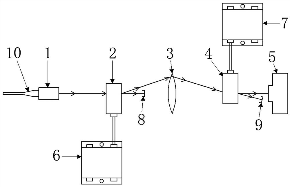
[0015] A laser frequency scanning device, comprising a fiber collimator 1, a first acousto-optic modulator 2, a convex lens 3, a second acousto-optic modulator 4, an avalanche photodetector 5, a first voltage-controlled oscillator 6, a second voltage-controlled oscillator controlled oscillator 7, the first beam collection pool 8, the second beam collection pool 9, an oscilloscope;

[0016] Wherein, the output end of the fiber collimator 1 is opposite to the input end of the first AOM 2; a focal length is set between the output end of the first AOM 2 and the input end of the second AOM 4. 100mm convex lens 3; the first AOM 2 and the second AOM 4 are located at twice the focal length of the convex lens 3; the output end of the second AOM 4 is facing the incident end of the avalanche photodetector 5 The output end of avalanche photodetector 5 is connected with the input end of oscilloscope; The output end of the first voltage-controlled oscillator 6 is connected with the modulati...


PUM


Abstract

The invention relates to a laser frequency scanning technology, in particular to a laser frequency scanning device and method. According to the laser frequency scanning device and method, the problemthat through an existing laser frequency scanning technology, the frequency of an exploring laser subjected to frequency scanning is substantially shifted, and consequently, principle resonance is caused is solved. The laser frequency scanning device comprises an optical fiber collimator, a first acousto-optic modulator, a convex lens, a second acousto-optic modulator, an avalanche photodetector,a first pressure-controlled oscillator, a second pressure-controlled oscillator, a first light beam collection pool, a second light beam collection pool and an oscilloscope; the emergence end of the optical fiber collimator directly faces the incidence end of the first acousto-optic modulator; the convex lens with the focal length being 100 mm is arranged between the emergence end of the first acousto-optic modulator and the incidence end of the second acousto-optic modulator; the first acousto-optic modulator and the second acousto-optic modulator are located on the double focus length of theconvex lens; and the emergence end of the second acousto-optic modulator directly faces the incidence end of the avalanche photodetector. The laser frequency scanning device and method are suitable for laser frequency scanning.

Description

technical field [0001] The invention relates to laser frequency scanning technology, in particular to a laser frequency scanning device and method. Background technique [0002] Ultracold atomic samples are widely used in precision measurement, ultracold chemistry, quantum gases, ultracold molecules, quantum information, atomic clocks and other fields. Magneto-optical trap is one of the most mature technologies for preparing ultracold atomic samples. By detecting the quantity and density of ultracold atomic samples in the magneto-optical trap, the parameter measurement and optimization of the magneto-optical trap can be realized. When detecting the quantity and density of ultracold atomic samples in the magneto-optical trap, it is required that the direction of the detection laser cannot be changed while scanning the frequency of the detection laser. In order to meet the above requirements, the method of double-passing the acousto-optic modulator is generally used to scan ...

Claims


Application Information

Patent Timeline
Patent Type & Authority Patents(China)
IPC IPC(8): G01N21/31G01N21/39G02F1/11
CPCG01N21/3103G01N21/39G02F1/11
Inventor 刘文良马杰武寄洲肖连团贾锁堂
Owner SHANXI UNIV
Why Eureka
Try Eureka